Monday, February 16, 2015

FRC 4992 Final week. Introducing Admiral Grace Hopper.

We are into the home stretch of the FRC "build season" and all of the planning, testing and pre-assembly came together during the last week as the students finally completed the base and attached the lift, winch and arm mechanisms to complete our entry. The team worked hard throughout January and also learned a great deal about design and engineering. I was gratified to see the team using our own desktop CNC mill to make aluminum parts and our new 3D printer to make plastic parts to help bring it all together.

The team also decided to draw inspiration from one of the most important people in the history of modern technology and name the robot after her. The well crafted autobiography of Admiral Grace Hopper by Gillian Jacobs will help you to see why the team chose this name.


Programming the Harvard Mark 2 computer must have been a daunting task. Many of the challenges must have been unanticipated. Building an FRC robot is like that too. Many of our challenges could have been more easily overcome through better planning and better organization and of course some just could not have been anticipated. In our second season I have come to realize that it will be necessary to codify better preparation and organization so that the planning and building will go smooth from year to year. This work is necessary because the team of students will change every year as the younger ones gain more experience and the older ones graduate and leave. At this point, with one day left to work on the robot, I am left thinking about this past fall semester and how to make it all work again from year to year. As a teacher it is easy to dream up a curriculum and start designing lessons but another challenge here is that this is a club. The students attend, or don't, depending on how they feel about the activity. If the pre-build season club meetings are all about lessons and skill development the students may feel it is too much like another class. The organization of the team will need to be such that the learning and skill development is student driven. They must feel the need to learn and practice skills through a will to succeed and perform well at a later date. A tough task with a generation so used to immediate gratification.

Admiral Grace Hopper is a good name for a robot. Hopefully it will make the students reflect on an era when solutions took methodical planning and months of work to accomplish. And hopefully they will ponder the outright determination it takes to start out being rejected from the navy for being too old and too small and to work your way up to the rank of admiral.

Saturday, January 17, 2015

FRC 4992 Learn by doing mock-up

It is week 2 in the FRC 2015 build season and team 4992 has made some great plans for a drive and lift system. We were at school all day today working on plans and looking for parts. Many of the parts we ordered earlier this week will not be in until next week but I wanted to make something happen. I challenged the students to build a mock up lift system so that we could look at the pitfalls and challenges. We took the ball grabber off of last years robot and turned it upside down to use as a winch. Up-rights out of wood and nylon rope from the back of my van completed the build.
I enjoyed watching the students work on this project and it is easy to see that this is the best kind of learning. We could see it work - sort of. We could use the mock-up to discuss and further refine the plans for the competition robot. We could see the students learn about making plans that are accurate and that use materials that can be sourced.

If you read my posts about the build season last year you will see that I was the lone adult working with this group during the build season. This year there are 2 other adults. What a difference! Thank you team 4992 mentors.

Wednesday, December 31, 2014

A first look at the Digispark Pro

The ATTiny85 Arduino in my last post was based on the Paperduino - which in turn is based on the Digispark board from Digistump.com.  They had a Kickstarter campaign going for the Digispark Pro kit. You could order these tiny Arduino compatible microcontroller boards along with an impressive array of shields. I ordered a couple of Pro boards along with a few different shield kits and they finally arrived a few weeks ago. I've had a bit of spare time so I was able to put together a couple of shields and try out this board.

Pictured are the Digispark Pro board, DigiLED shield and Charlieplex shield.

The Digispark Pro board comes ready to use. You can solder on some supplied female headers to do prototyping or to plug in shields. The USB connection is USB Micro-B. Like the ATTiny 85 the board is unplugged when you start uploading and plugged in when the IDE gives the prompt message. And just like the ATTiny 85, some of the i/o lines, pins 3 & 4 in this case,  are also used for serial communication which means that some circuits will interfere. When this happens the circuit or shield needs to be disconnected during upload and then reconnected after the software is loaded. This can slow down debugging. This board uses an Atmel Attiny85 MCU with about 6 KB of flash memory.


The DigiLED shield kit comes with what looks like an RGB LED. In fact the device is a smart RGB LED or WS2812 compatible LED. These LEDs have become very popular with hobbyists because they contain registers and other circuitry that allows them to be daisy chained. A large number of LEDs can be controlled using just 3 wires! Power, Ground and Data. The price of these LEDs is under a dollar. In fact you can buy a NeoPixel ring with 60 LEDs prewired. The provided code is hard on the eyes. Its easy to make loops that fade each colour in and out for a more pleasing demo.

The Charlieplex shield shows how to control 20 LEDs using just 6 data lines. The Charlieplex trick is to remember that a digital i/o pin can have 2 states in Output, 0 or 1 (ground or +V) and that when set as "Input" the pin really has a third state called Hi Z or high impedence. In the Hi Z input state the pin acts as neither ground or +5 V and more like an open circuit. The Charlieplex LEDS are cleverly wired so that each LED is separately addressable via a combination 1 Hi output and 1 Low output while keeping the rest of the pins at Hi Z.

The Digispark Pro board looks like it could be used in the classroom as long as the students are careful and patient. The low price means that the odd burn out won't be a major pain to the budget. It will be interesting to see how the unit fairs doing some of the basic Arduino tutorials we use in grade 10 and 11.

Monday, December 1, 2014

ATTiny85 Arduino part 2, One Potato, Two Potato, Three Potato, more

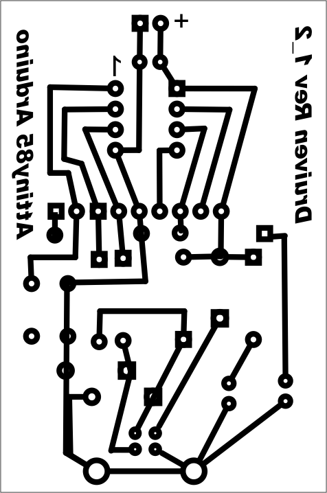
I put the ATTiny85 Arduino project aside for a few weeks and when I picked up my circuit board again I used another laptop, my trusty Samsung Netbook actually. I followed procedure carefully and sure enough it worked first time and every time! I made a few minor adjustments to the PCB pattern and printed off some copies for my grade 12 Computer Studies class. We etched the boards using the Toner Transfer method and got some good looking PCBs. A few days later the components were soldered onto the boards and the Boot Loader burned into a bunch of ATTiny85 chips. Next thing you know: one potato, two potato, three potato more -

Congratulations to the grade 12 class that built these. Excellent work.

Here are the instructions I gave to the class:

INSTRUCTIONS
STEP 1
Manufacture the circuit board using the trace layout given following the classroom procedure. You may want to add 1/8 inch holes in each corner so that your board can be mounted using 4/40 screws at a later date.


STEP 2
Familiarize yourself with the schematic diagram and parts placement.
Identify the following parts:
  • USB signal
  • Power
  • Reset
  • i/o


STEP 3
Place the components and solder them in place in the following order. Clip the excess leads after each set of components is soldered.
  • Capacitors
  • 8 pin socket
  • 1.5kΩ resistors
  • 1N4148
  • 22Ω resistors
  • 3.6V zener diodes
  • LEDs
  • reset pushbutton
  • 9 pin header
  • USB socket


STEP 4
Use a multimeter to check for shorts between traces. Notice that the USB power and signal traces are very close together and a USB short could affect your computer. If there are no shorts connect your Atiny85 Arduino via USB to a laptop for a moment. The green power LED should glow (and hopefully nothing else will happen).


STEP 5
Unzip the Digispark Arduino IDE and locate the directory in the installs directory on a school laptop.

STEP 6
Use the InstallDriver utility inside /DigisparkArduino-Win32/DigisparkWindowsDriver to install the driver.

STEP 7
Run the Arduino IDE inside of /DigisparkArduino-Win32/Digispark-Arduino-1.0.4/
  • Do not connect your Atiny85 Arduino to the computer yet.
  • Under Tools choose Board and choose Digispark (Tiny Core).
  • Under Tools choose Programmer and choose Digispark.
  • Under File choose Examples and choose Digispark_Examples and choose Start.
  • Click the upload button and watch the message area at the bottom of the IDE.
  • Plug in your Atiny85 Arduino when the “Plug in device now . . .” message appears. Pin1 (sometimes called PB1) is pin 6 on the chip. Your built in red LED is connected to this pin. The program should cycle the LED on and off at 1 Hz.

Handy Reference Chart
pin Pin Analog
1 Reset

2 3 Input 3
3 4 Input 2
4 Gnd

5 0 PWM,AREF,MOSI
6 1 PWM, MISO
7 2 Input 1, SCK
8 VCC


Here is a pdf file containing a sheet of  16 pcb layouts.


Monday, July 21, 2014

ATtiny85 Arduino part 1

I was inspired by the Paperduino Tiny project on Instructables and the Digispark board from Digistump to make my own Arduino board based on the Atmel ATtiny85 chip. The Paperduino project might be too hard for high school students with limited soldering and engineering experience but we can make our own circuit boards in the classroom.

I used the USBtinyISP AVR programmer to load the micronucleus boot loader onto a couple of ATtiny85 chips purchased from Abra Electronics.
NOTE: The High fuse should set to 0xdd. The instructions here indicate that burning with or without RSTDSBL can be tried but the chip burned with RSTDSBL (hfuse:w:0x5d:m) did not function afterwards and AVRDUDE (see below) does not recognize it any more.
AVRDUDE is a DOS based program that comes as a part of WINAVR. The DOS commands are rather long so I copied them into notepad and saved them as .bat files. To run the DOS command just put the .bat file into the same directory as the .hex file and type the name of the .bat file in from DOS in that directory. The complete command also needs to be modified to reflect the ASP used.
avrdude -c usbtiny -p t85 -U flash:w:micronucleus-1.06-upgrade.hex -U lfuse:w:0xe1:m -U hfuse:w:0xdd:m -U efuse:w:0xfe:m
Here is the breadboarded Paperduino circuit.


The circuit board to the right contains the circuitry necessary to connect the USBTINY AVR to the ATtiny85 chip on the bottom half and a USB breakout at the top. USB sockets do not plug in to breadboards so some kind of adaptor was required.

I used Fritzing to lay out the circuit board. From Fritzing I export an etchable svg file which I bring into Corel Draw so that I can make the traces thicker and add text.


I like the way the Paperduino brings out the ATtiny85 pins to a female header so I did the same thing below the chip on my board. 22 gauge hookup wire can be used to connect to a breadboard.

The Digispark Arduino IDE package contains the driver installation. The red LED is on Digital pin 1 so the Blink program with the output set to pin 1 is all that is needed to verify operation. Change the Programmer to Digispark and the Board to Digispark (Tiny Core). You start with the board unplugged and after hitting Upload the IDE tells you to plug in the board. The breadboard version worked once and the circuit board a couple of times. Most of the time I end up with a USB Not Recognized warning from Windows. The computer sees it as an unknown device. Despite this the code has loaded on three occasions. I suspect something is going on in Windows.

Despite having problems with the Windows driver it did work a couple of times and my red LED is happily blinking away as I write this. I think of Blink as a kind of Hello World on my own home-made ATtiny85 based Arduino board. Nice!

Tuesday, July 1, 2014

8 x 8 LED matrix using 4017 and Arduino


  This years grade 12 Computer Engineering summative  challenge asked the students to control an 8 x 8 LED matrix using a 4017 decade counter to "scan" the columns and an Arduino to "sink" the rows. Examine the schematic below and you will see that control of any particular LED in the matrix is a matter of making the 4017 pin high and the Arduino pin low. The 4017 chip counts from one to ten and then resets but setting pin 15 high also causes a reset. Connecting pin 9 to 15 causes the ninth count to reset the 4017 back to 1. Our decade counter ends up counting one to eight. Clock pulses on pin 14 make the 4017 count up. The fastest possible digitalWrite(2, HIGH); digitalWrite(2, LOW) cycle from the Arduino is enough for the 4017 to respond.
   The usual logic for LED control is to use the Arduino pins to "source" the LED - to go high or "on". An examination of most Logic and microprocessor circuitry specifications will show that these circuits have a higher capacity to "sink" current. That means you need to connect the LED anode to power and the cathode to the Arduino pin. Making the pin low is the same as ground so a zero on the pin will cause the LED to glow. This is a reversal in our usual logic where one = on and zero = off. In this case we need to keep the Arduino pins high and send them low to turn on the LED.

Parts
Arduino UNO
Breadboard
4017
BL-M07C881 - 8x8 LED matrix
8 x 300 ohm resistors (I used an 8 x 470 ohm DIP)
jumper wires (I cut most to length to keep it neat)

Here are the pin-outs for the LED matrix:


STEP 1: Wiring

Matrix             4017
5 -----------------> 3
6 -----------------> 2
7 -----------------> 4
8 -----------------> 7
13 ---------------> 6
14 ---------------> 5
15 ---------------> 1
16 ---------------> 10

Matrix             Arduino via a current limiting resistor.
1 -----------------> 6
2 -----------------> 7
3 -----------------> 8
4 -----------------> 9
12 ---------------> 10
11 ---------------> 11
10 ---------------> 12
9 -----------------> 13

Don't forget to wire Arduino pin 2 to 4017 pin 14 for a clk input and pin 3 on the Arduino to to pin 6 on the 4017 to detect a count of 8. Wire 5V from the Arduino to pin 16 on the 4017 and tie the ground to 4017 pins 8 and 13.


Step 2 Testing

   Use Blink but change the output pin to 2. Disconnect the wires going to the Arduino pins 6 to 13 . Blink will pulse the 4017 slowly. Connect any one of the 8 disconnected leads to ground. The LEDs on that row should light up one after another. If you reduce the delay the LEDs will light quicker and quicker. A very short delay will make it seem as though the entire row is lit. POV or Persistence of Vision makes it seem as though all 8 LEDs are on at the same time when really only one is on at any given time. You will use this later to minimize the current draw on your circuit.

/*
  Blink
  Turns on an LED on for one second, then off for one second, repeatedly.
 
  This example code is in the public domain.
 */

 
// Pin 2 is our 4017 clock.
int clk = 2;

// the setup routine runs once when you press reset:
void setup() {                
  // initialize the digital pin as an output.
  pinMode(clk, OUTPUT);     
}

// the loop routine runs over and over again forever:
void loop() {
  digitalWrite(clk, HIGH);   // turn the LED on (HIGH is the voltage level)
  delay(1000);               // wait for a second
  digitalWrite(clk, LOW);    // turn the LED off by making the voltage LOW
  delay(1000);               // wait for a second
}

Step 3 Programming

In the checkmark example below I used an array to 'map' which LEDs I wanted to come on.

/*
 Test 4
 Test 4 Checkmark
 */
int del = 0; // clk width
int chk = 0; // check for reset signal
int row = 1; // row
int ct = 0; //array counter
int pattern[] = {0,0,0,0,0,0,0,1,
                       0,0,0,0,0,0,1,0,
                       0,0,0,0,0,1,0,0,
                       1,0,0,0,1,0,0,0,
                       0,1,0,1,0,0,0,0,
                       0,0,1,0,0,0,0,0,
                       0,0,0,0,0,0,0,0,
                       0,0,0,0,0,0,0,0};
int sensorPin = 3;
void setup() {
  Serial.begin(9600);
  Serial.println("Start");
  // initialize the digital pins as an output.
  pinMode(2, OUTPUT); //clk out
  pinMode(3, INPUT); // reset sense
  for (int i = 6; i <=13; i++){
    pinMode(i, OUTPUT);  
  }
  for (row = 6; row <=13; row++){
    digitalWrite(row, HIGH);  
  }
  reset();
} // setup

void loop() {
    for (row = 6; row<=13; row++){
      for(int i=1; i<=8; i++){
        if(pattern[ct]==1){    
        digitalWrite(row, 0);
        pulse();
        delay(2);
        digitalWrite(row, 1);
        }
        else{
          pulse();
        }
        ct++;
    }
  }
ct=0;
}

void pulse(){
      digitalWrite(2, HIGH);
      delay(del);            
      digitalWrite(2, LOW);  
      delay(del);  
      // 8 pulses for 8 rows
}

void reset (){
  for (int i = 1; i<=9; i++){
    pulse();
    Serial.println(i);
    chk = digitalRead(sensorPin);
    Serial.println(chk);
    if (chk==1){  
      return;
    } // if
  } // for
} // function

If I were to do this again I would reverse the zeros and ones in pattern[] and then instead of using an if statement to check for a 1 I could have simply written the contents of the array out.
for(int i=1; i<=8; i++){  
        digitalWrite(row, pattern(ct));
        pulse();
        delay(2);
        digitalWrite(row, 1);
        }
       ct++;
etc.

Another interesting experiment would be using Arduino Port D (pins 0 to 7) to control all 8 rows with one command. I usually avoid using pins 0 and 1 but in this case it seems sensible to use them.

Step 4 Challenge

The challenge that earned top marks was to make a set of initials scroll across the matrix. In the example below I used a 2 dimensional array to 'map' the LEDs in a way that would make shifting them easier.
/*
 Test 5
 Scrolling Checkmark
 Implements 2 dimensional array
 */
int del = 0; // clk width
int chk = 0; // check for reset signal
int row = 1; // row
int ct = 0; //array counter

int pattern[8][16] = {
  {0,0,0,0,0,0,0,1,0,0,0,0,0,0,0,1},
  {0,0,0,0,0,0,1,0,0,0,0,0,0,0,1,0},
  {0,0,0,0,0,1,0,0,0,0,0,0,0,1,0,0},
  {1,0,0,0,1,0,0,0,1,0,0,0,1,0,0,0},
  {0,1,0,1,0,0,0,0,0,1,0,1,0,0,0,0},
  {0,0,1,0,0,0,0,0,0,0,1,0,0,0,0,0},
  {0,0,0,0,0,0,0,0,0,0,0,0,0,0,0,0},
  {0,0,0,0,0,0,0,0,0,0,0,0,0,0,0,0}
};
int ab=0;
int sensorPin = 3;
void setup() {
  Serial.begin(9600);
  Serial.println("Start");
  // initialize the digital pins as an output.
  pinMode(2, OUTPUT); //clk out
  pinMode(3, INPUT); // reset sense
  for (int i = 6; i <=13; i++){
    pinMode(i, OUTPUT);  
  }
  for (row = 6; row <=13; row++){
    digitalWrite(row, HIGH);  
  }
  reset();
} // setup

void loop() {
  for(ct=0; ct<8 animation="" croll="" ct="" p="">    for (int draw = 0; draw<5 down="" draw="" p="" slow="">      for(int row=0; row<8 p="" row="">        for(int col=0; col<8 col="" p="">          if(pattern[row][col+ct]==1){    
            digitalWrite(row+6, 0);
            pulse();
            delay(2);
            digitalWrite(row+6, 1);
          }
          else{
            pulse();
          }
        }//col
      } //row
    }//draw
  }// ct
} // main loop

void pulse(){
  digitalWrite(2, HIGH);
  delay(del);            
  digitalWrite(2, LOW);  
  delay(del);  
  // 8 pulses for 8 rows
}
/* The reset function is called once during setup.
 It pulses the 4017 until it detects an output from
 pin 6, indicating that the count is at 8 and the next pulse
 will be column 1. */
void reset (){
  for (int i = 1; i<=9; i++){
    pulse();
    Serial.println(i);
    chk = digitalRead(sensorPin);
    Serial.println(chk);
    if (chk==1){   // 4017 pin 6 is high
      return; // No need to continue
    } // if
  } // for
} // function

The array is twice as wide as the matrix to allow a frame 'buffer'. There are probably better ways to manipulate the array to do this.


Monday, March 31, 2014

The First Competitions

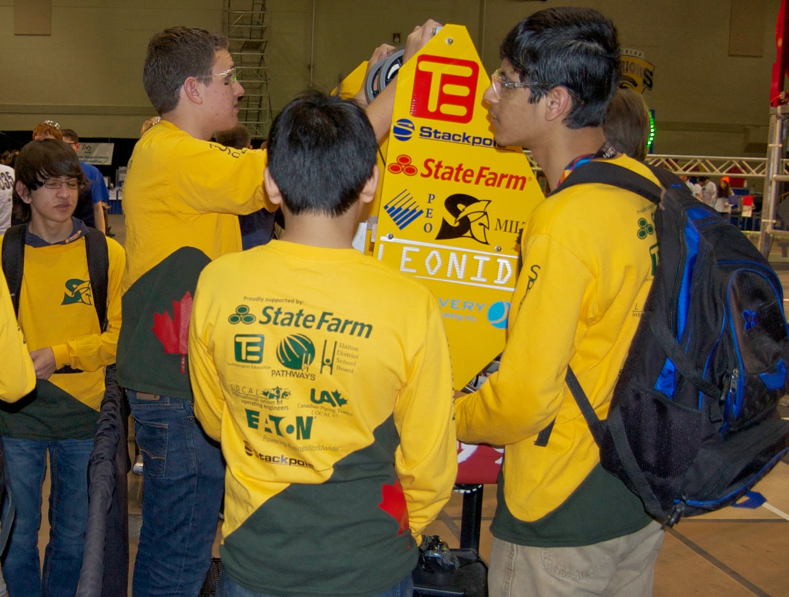
Team 4992, the Spartans competed at the First Waterloo Competition March 20 - 22 and at the North Bay Competition March 27 - 29. Both competitions provided the students with many opportunities to grow, learn and mature. In their first 2 outings they got to see what happens at a competition both behind the scenes and on the field. The team was able to come together and work to solve problems and strategize through a combination of observation and discussion.

On Wednesday March 19th one other student and I took the robot along with a toolbox and several boxes of spare parts to the Physical Education building at the University of Waterloo where each team is given a 10 foot by 10 foot "pit" area with a table and power. The next day we set about making the area useful for robot repair and maintenance and discovered we needed a way to stow all of our coats and bags. That night I bought some plastic shelving and a collapsable picnic canopy to help organize and define our space.

Our first inspection revealed a misunderstanding in the pneumatic circuit setup that required a rebuild of the entire high pressure side of the system. With the loan of a couple of parts from 1334, our friends in Oakville, we had the bot up and running in time to do some practice rounds on Thursday.


Friday saw the robot performing as required while the students quickly developed a deeper understanding of the Aerial Assist game play. Due to the scoring structure of this years game alliances of 3 teams were able to score very high by passing the ball from human to robot to robot then over the truss to human to robot to high goal. Our team quickly found their place as the lead robot, taking the ball from the first human player and passing it quickly to the next bot. Most of the other alliances at Waterloo concentrated on the same cycle and by Saturday morning we saw scores approaching 300 points. The repetitive cycling made for a dramatic and enjoyable show for the audience and relied on driver skill and robot performance.

4992 finished the round robin with a rank of 20 out of 30 and was picked by the teams from Rick Hansen Secondary in Mississauga and St Davids in Waterloo to form an alliance Saturday afternoon. They continued to play the rapid high score cycling game which saw them through right to the final match where they were defeated. You can imagine the excitement of the team, the parents and the teachers as the alliance progressed through the afternoon. I think we hurt our faces smiling so much and many of us were hoarse and deaf from the shouting.


The competition in Waterloo relied on parent volunteers driving several student to and from Waterloo each day. The competition in North Bay was organized centrally by the school board since all 7 Halton teams appeared and we would need buses and hotel rooms. Generous donations from our sponsors made it possible.

The teams at the North Bay event were much more aggressive about defence and seemed to enjoy brute force pushing and shoving over the finesse and skill seen at Waterloo and so we saw very few high scoring rounds. Many more bots seemed to be plagued with electrical and mechanical malfunctions as well. Our robot made it through to the elimination rounds on Saturday afternoon, forming an alliance with our cross town mentors from Milton District High School and Burlington Central High School making our alliance the "Halton" alliance. Unfortunately the pushing and shoving continued along with the break downs and our alliance lost 0 - 2  while the afternoon was young.


The students should feel proud of what they have achieved and they will certainly have gained many of the skills and much of the knowledge they need to continue with First Robotics next year. We had some help from 2 Stackpole International engineers, Andrew and Kelly and from a Discovery Precision Engineering machinist (team member parent) but keeping the club going will require some more mentors to help with the team organization and teaching. It was a lot of fun doing it all myself but very tiring and the team was often limited by just one adult in the room. We will be able to get a better start next year by revisiting this years challenge and doing some design work around Aerial Assist for practice.