Sunday, January 15, 2023

Balance on a Teeter totter

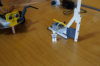
 This year the FRC robots need to balance on a teeter-totter affair on the playing field. 


This video shows an autonomous ESP32 robot attempting to balance itself. I don’t have a gyro at home so I used a 3 axis compass (which gets thrown off when the robot changes direction). I think it will be easier to do with a real gyro. The drive system is cheap continuous rotation servos driven by an ESP32. It is next to impossible to get the servos synced at the same power level and to slow them down, so, again with a real robot that drives straight and slow this enterprise would be improved. Once I sorted out some power issues and a bum servo it was satisfying to see it work.

The code is a simple if structure.

If the x axis is greater than 100 (pointed up) drive forward a bit and wait a bit;
Else If the x axis is less than -100 (pointed down) back up a bit and wait a bit;
Else wait a bit;

Saturday, March 12, 2022

ESP32 mini home robot for E-learning


Last school year in Ontario all the classes were on line and clubs and sports teams just weren't happening. The team at CKSS, Sparbotics, Team 4992 continued to meet on line through the fall of 2021 and spring of 2022. Team members entered 3 FIRST Robotics virtual challenges under the Inifinite Recharge at Home banner. 20 team members also took home a desktop robot kit I designed around the ESP32 chip. The students learned some basic i/o skills (much like the Arduino) and then explored the Wifi capabilities following a set of instructions and meeting online with questions and observations. The school year culminated with the Mission to Mars challenge which asked the students to move a lego "cargo" brick between 2 stations.

High School students had great difficulty with the online learning environment. Students learn best by doing and the "doing" needs to be in an environment they are accustomed to. They work best with their peers at solving problems and asking questions. They liked working on the Infinite Recharge at Home challenges together but many lost enthusiasm with the ESP32 because they were working alone, unable to see each other and see the other robots. The ESP32 challenges would have worked better in an immersive virtual environment with VR glasses or cameras showing the students, their screens and their hands working on the robots. I can't imagine getting to place where that could happen given the amount of technology required and the privacy concerns it would raise.


Tuesday, March 30, 2021

Interesting facts and ideas from a People for Education Report titled Technology in Schools.

This People for Education Report is an important read.

From the report:
"Up to now, future-ready skills and competencies have gone by a variety of labels including soft skills, 21st century skills, transferable skills, and global competencies (British Columbia Ministry of Education, 2017; OECD, 2018; RBC, 2018; Waddell et al., 2018). People for Education refers to them as The New Basics."

1. Thinking Creatively and critically
2. Developing a Sense of Self and Society
3. Communicating Effectively
4. Learning to learn
5. Collaborating

In Ontario "future ready" skills are referred to by the Ministry of Education as "transferable skills" including, 
1. critical thinking
2. social-emotional skills
3. adaptability
4. digital literacy
5. collaboration

While 1, 2 and 5 in both lists are a match, 3 & 4 are not. Adaptability & Digital Literacy are both open to interpretation more than the other 3 so it remains to be seen how these terms will be used in curriculum documents.


Thursday, April 9, 2020

Converting a 2418 Desktop CNC to Laser part 2

In part 1 I talked about the mechanical and wiring portions of the conversion. In part 2 I will discuss software settings and usage along with operation. Now that the laser is mounted and wired it's time to burn some wood!

The LaserGrbl software lets you change some of the Grbl firmware settings on the controller board. I left everything as is except $3 which I had to invert so that the X and Y movements on the mill matched the output from the software.


I started out powering the laser using an old 1 amp variable voltage power supply I built many years ago. I figured 12 volts, 5.5 W, that's less then 1/2 an amp right? Wrong. My initial try with the included griffin example file (look for the sample SVG - G Code folder) went well but after that the laser output started becoming erratic and would trail off after a few seconds. A quick test with a multimeter showed the power supply voltage was dropping to just 3 or 4 volts! 


A week or so later when I got a fixed 12V 5A power supply I was able to start experimenting again. LaserGRBL lets you make custom buttons. Right click and choose Add Custom Button in the button bar at the bottom. This one turns the laser on at low power (25/255).


I do not have limit switches so Grbl uses the XY position at power on as home. I make sure the laser is positioned on the lower left area of the workspace when I power up and then use this low power laser on/off button to give me a low power dot to position the work piece. Getting the laser focused was tough because even at the low power setting the wood begins to burn after a few seconds. Focusing took some patience as I had to keep moving a scrap piece while turning the focusing ring and looking for the smallest dot. It paid off because now it draws very sharp lines. I am using scrap pieces of 1/8" mahogany construction grade plywood.


After experimenting with laser power settings and feed speeds I came up with a combination that gave good clean lines and corners. I drew the iceboat outline by tracing a photo using Aspire and then exporting it in svg format. LaserGrbl generated the CNC code from the .svg file. On import the software asks for the feed speed and laser power settings. The code did not complete the lines in a logical order, often wasting time jogging back and forth. I still need to investigate why this is happening. 

Doing something with grey scale in it like a photo is the next challenge. Wood is either burned or not. LaserGrbl creates grey scale areas by using dots, the more space between the dots, the lighter the shade. The trick seems to be feeding LaserGrbl with a photo that is comprised of a narrow scale from light to medium grey.


I imported this grey scale file to try some test strips at different feeds and power settings.


Coming up I'll experiment with photos some more and then move on to cutting paper and wood.


Thursday, March 26, 2020

Converting a 2418 Desktop CNC to Laser part 1

I had been toying with the idea of swapping the spindle motor for a laser on my 2418 desktop CNC machine. The Woodpecker 2.6 controller has a laser output which is straight ON/OFF but I wanted to use a 5.5 W PWM controlled 450 nm blue laser so that I could adjust the laser power on the fly. The Laser I found on line is made by WonVon and comes with a controller with 12V and TTL (PWM) inputs. The software I found is similar to the GRBL software I used for CNC work and is called LaserGRBL v3.1.2.  I believe what I found out will work for any PWM controller laser running any CNC/Laser type software using the GRBL controller.

I discovered that the Atmega 328 that is the brains on the Woodpecker is the same chip used on an Arduino. It had a boot loader called GRBL 0.9 but I needed to upgrade to 1.1 to be able to control a laser. There are a lot of instructions and discussions available showing how to do this on an Arduino but nothing clear for the Woodpecker. Fortunately, there is a utility built into LaserGRBL that flashes the 1.1 firmware (bootloader) with the push of a button. The USB interface to the Woodpecker uses a CH340 chip and LaserGRBL also has a utility to install the driver. Both utilities are in the menu bar under Tools.

I thought that the PWM pin that the S command (laser intensity) in G code was available on the 34 pin header. Sadly I was mistaken. The signal originates from the D11 pin on the Atmega 328. On the Woodpecker the 328 is too small to solder directly but D11 connects to the big power MOSFET that controls the spindle. You can see I soldered a short piece of blue solid 22 gauge wire directly to the MOSFET signal pin in the photo below. The brown ground wire is a female 0.1 jumper end. Both of these are spliced to the PWM input. White is PWM + and yellow is ground. The other connector in the photo with yellow and white wires connect to an external 12V DC power supply. On this connector yellow is + and white is ground.


I also thought it would be nice to easily switch between Laser and Spindle mode on the 2418. I hoped the spindle motor clamp was the right size to also hold the laser. Again, sadly I was mistaken. Fortunately I found that Brandon Piner had published some stl files on Hackaday that showed promise. His CNC Z Mount allows the easy exchange of tools. Brandon also put his files on Thingverse where a remix by wb-maker gave me a mount for my laser. Now all I needed was a mount for my spindle motor. I drew this out in Inventor and then got all three parts, the Z Mount, the laser mount and the spindle mount printed.

The next 3 photos show the Z Mount, the Z mount with the laser attached and the Z mount with the spindle mount attached.


In order to use the new Z mount I had to push the 4 bearings and lead screw adapter out of the original spindle mount and then push them back into the new Z mount. I was careful to use objects like bolts that were the same diameter as the bearing or adapter to gently tap them out/in. To push them out I supported the block on a solid surface with a hole large enough to receive the bearing or adapter. To push them in I made sure the parts had a thin coat of oil and were held square to the hole. No excessive force was needed.

In part 2 I will talk about getting the software set up and using LaserGRBL to do line art and grey scale bitmaps.


Thursday, July 5, 2018

Tiny Duino board on a desktop CNC


This photo shows 3 versions of the Tiny Duino board I first described in July 2014. The board on the right is laid out in Fritzing and etched using the toner transfer method to create a mask. The other 2 boards were laid out using Eagle and produced on my little desktop CNC machine seen in my October 2017 post. The default components in Eagle are good for commercial production but created pads and lines that were too fine for this method.

The first step was to learn a little about Eagle CAD. Eagle is free for hobbyists making small single sided or double sided circuit boards. You can edit components by opening the library containing the component and then double-clicking the package file for the component. I made the pads bigger and the drill holes smaller. Later when the CNC machine does the drilling the hole size is determined by the physical drill you place in the machine. I used save-as and put "my" in front of the library name to make it easier to find later. You will need to open your new libraries using the Library manager in order to be able to use them. You can find some tutorials online to learn more about this. In Eagle 8.6 the component libraries are in /cache/lbr. I put the libraries I edited into Github. Library files contain large collections of components. I only edited the components used on the TinyDuino.

Since I had already laid out the TinyDuino board for etching I found it quicker to place the components on a new board in Eagle and then create the traces. This takes 2 steps. Firstly use Signal to join the components and then Route to create the trace. You can move the traces around and create bends. I made the traces 20 to 30 wide. Ground traces that are wider then the rest make it easy to identify ground later on. Make sure they are all on the Bottom since you are making a single-sided board.

TinyDuino layout

The Make Your Own PCBs on an Inexpensive Desktop CNC machine Instructable article by davr.org helped me figure out how to use EagleCAD to generate the G code for my own desktop cnc mill. The pcb-gcode-EagleCAD plugin file contains a good manual in the docs folder to help you figure out the next steps. The plugin uses Processing and also generates a graphic so that you can double check your G Code. I used the single pass isolation mode and a 0.5mm end mill. Keep the spindle speed high, the feed rate low and run the code with the bit cutting air first to make sure the code works.

G code visualizer from the Eagle plugin.

Everything about this project required learning, trial and error and time. I was very pleased to see the final TinyDuino boards being cut. There were several trials until I got everything right. I think it really helped to do this with a circuit board that I am already very familiar with. I feel more confident that I can use this method to make a prototype circuit board in the future.

Friday, October 27, 2017

Retired!

Happy Friday . . if you happen to be reading this on a Friday! So I am officially retired from teaching. I sleep in, read books, do errands and wonder where the day went! I still mentor for FRC team 4992 so I'm back in to the school two afternoons a week. I will do some supply work but otherwise my schedule is pretty clear. I planned to spend some more time on this blog and perhaps widen the scope a little but here it is already the end of October and I am finally sitting down to get at it. The first order at hand was to be a comprehensive list of Microntrollers but thanks to ZeusGuy, Graeme Bartlett et al there is now a nice long list on Wikipedia. Good job people.

The teachers in my department all pitched in and got me this neat little desktop CNC machine for my retirement gift. In the next couple of blog posts I'll talk about using Eagle CAD to generate G code files to make small circuit boards on this machine.


Saturday, August 19, 2017

A First Look at the mBot

Recently our school board received some mBots from Makeblock to try out in the classroom. The mBot is a small autonomous Arduino Uno based rover educational platform that can be programmed in Arduino C or a Scratch derivative called mBlock (mBlockly on an iPad).

The kit comes with the following:
mCore main board, DC motors, wheels, chassis, battery holder, hardware
INPUTs: Light Sensor, Button and IR Receiver on board and an Ultrasonic Sensor module and a Line Follower Sensor Module. The modules plug in via RJ25.
OUTPUTS: 2 RGB LEDs, Buzzer, IR Transmitter, 2 motor ports on board.
Each kit comes with either a WiFi or Bluetooth module that sits on mainboard headers.
POWER: Standard female DC power jack or standard Lithium 2.0 connector.

The sensors plug in to RJ25 jacks and the motors have 2 pin JST connections. There are 4 available RJ25 jacks. 1 and 2 contain Arduino I/O pins 9 through 12. 3 and 4 contain Arduino A0 through A3 pins. There is an ICSP header. There are no other I/O ports supplied. There are solder points for two 0.1" x 6 headers. On the left is A0, A1, A2, A3, SDA, SCL and on the right is GND, 5V, 9, 10, 11, 12.

The kit also comes with an IR remote (requires a CR2025 cell), a USB cable and a hex driver for assembly. Putting it together takes no time. The main board needs to be removed to change batteries if you are using AA cells. The main board supports charging Lithium batteries which are not included but might make a wise investment considering the way DC motors use up battery power.

Straight out of the box I had the mBot running in no time. The default program lets you control the mBot via Bluetooth (or WiFi), or via IR or it can be set to autonomous run around and avoid obstacles mode or line-following mode. I like the mBlock IDE because you can quickly program the mBot using Scratch-like blocks and see the Arduino C code result in the right hand window. This makes for an easy transition for grade 9 or 10 students who have used Scratch and want to start coding in C.


I think the mBot is a good platform for teaching robotics, interfacing or Arduino to grade 9 and 10 students. The price is very good. We purchased a similar all-in-one platform a few years ago that needs to stay tethered via a USB cable to work. The old platform engages students but can be frustrating because the tether cable limits motion. The mBot should be operated on the floor but drops and kicks will be inevitable. The mBot is very robust. The metal chassis can handle some pain. Parts like wheels and DC motors are easy to replace. The kit comes in a handy reusable box that can hold the mBot after assembly and stack in a cupboard.

I usually shy away from endorsing products but this unit deserves mention for its competitive price and ease of use. I would recommend these to anyone starting out high school Computer Tech or Robotics classes. A class set might be impossible to budget in one year but as I always recommend - have a plan. Buy 2 or 3 a year. These units will do a great job at covering many of the learning outcomes in TEJ courses.

Sunday, June 5, 2016

The Internet of Things part 1, the Yun

In the Internet of Things series I will explore the use of WiFi enabled microprocessors like the Arduino Yun and Digispark Oak as tools that students can use to learn how to connect devices to the Internet. The connection of devices and machines to the Internet to allow man-machine and machine-machine interaction is now embodied in the phrase "the Internet of Things". There has been an explosion of interest in industry and commercial markets as the price of WiFi technology comes down. A corresponding surge in the hobby, DIY field can be seen with an ever growing number of products and online tutorials and projects. The Yun was first released in 2013 with the same form factor and IDE as the original Arduino. Recently we saw the release of the Raspberry Pi 3 which has 802.11n and Bluetooth built in. The Digispark Oak, the Omega Onion and a host of other products aimed at the hobbiest, DIY and developer fields are becoming available.

In this post I will write about my first few experiments with the Yun. In the next few posts I will describe early experiments with the Oak and other WiFi enabled microcontroller solutions. I hope to be able to conclude with a wish list for enabling students to learn about this technology in a clean and consistent manner. My early experience with the Yun and Oak indicate that the technology is not straight forward nor for the faint of heart. I hope to finally compare and contrast all the solutions that I tried out.

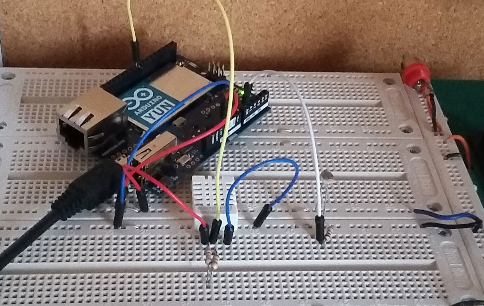
The first step as it is with any of these things is to follow the Getting Started tutorial that comes with the device. I found that I could connect the Yun easily to my home network (Linksys) or my experiment router (Belkin with no Internet). At school I should be able to connect to our public network since the Yun does not require any special settings at the router. Some familiarity with ip addressing and the Linux OS helps but is not necessary.

"The Arduino Yún is a microcontroller board based on the ATmega32u4 and the Atheros AR9331. The Atheros processor supports a Linux distribution based on OpenWrt named Linino OS. The board has built-in Ethernet and WiFi support, a USB-A port, micro-SD card slot, 20 digital input/output pins (7 of them can be used as PWM outputs and 12 as analog inputs), a 16 MHz crystal oscillator, a micro USB connection, an ICSP header, and 3 reset buttons." - from the Arduino.org website.

The Atheros processor communicates with the ATmega microcontroller using a technology called Ciao Core.  This technology is incorporated into the Bridge library which must be included in your sketches.

Step 2 involved using the Yun just like any other Arduino to verify the correct operation of the following devices:
1. Photoresistor in series with a fixed resistor to measure analog light levels.
    Photoresistor wiring from Arduino Tutorial.
2. DHT22 to measure temperature and humidity. DHT22 wiring from Make Nation.

The sketch worked perfectly using the open source DHT22 Arduino library.


Step 3 used the Weather Station tutorial in Marco Schwartz's book the Internet of Things with the Arduino Yun. The tutorial uses a website/software stack called Temboo as a go-between a Yun and cloud apps like Google docs. You will need to have a Temboo account and a Google account.

Marco's book is 2 years old and Google has changed the way docs are accessed. Instead of good old username and password Google now uses the oAuth protocol. The Temboo website uses apps they call choreos that enable the flow of data from the Yun to be entered onto a spreadsheet. In order to set up a connection you must now run an initialization oAuth choreo and a Finalize oAuth choreo. As you go through the process you collect a client id, app id and other tokens that have to be copied into your code. You can follow the Temboo tutorial which gives you some Arduino Yun code that works. You can find my code, which integrates the original code from the book and the Temboo tutorial on Github. https://github.com/mdruiven/Yun-Weather-Station. All the account information and tokens are in a separate file called TembooAccount.h. Make sure to change them to your own codes and information.

I found that I had to use my coding skills to solve a couple of issues. I think the level of complexity was medium to hard and beyond the average high school level. That said, I believe that senior high school students could tackle problems very similar to this one by following these directions and using my code. By similar I mean write some data to a spreadsheet collected from various sensors connected to a Yun. I think this has a very high cool factor and will encourage students, and others, to continue to learn and experiment with this technology.


Saturday, August 15, 2015

Rare and Cherished part 2

Now that the Pan Am and Para Pan Am games are over it is time to reflect on the experience I referred to on April 12, In that post I outlined a plan to allow students to use voluntary IT support work at the games as  high school coop hours. Over all this was a positive experience for the students but there were some hitches along the way.

Throughout May and June the students continued to self organize their on line and in person training and the collection of credentials from North York in Toronto. The students also received their shifts and it quickly became apparent that I had overlooked one important factor. Hours. High school students need to complete 180 hours on the job in order to earn their 2 credits. Most of the students did not have near enough shifts to make up these hours. Furthermore some students were conflicted out of the coop course by the necessity of summer make up credit classes. The students had to make up hours by taking on other coop positions at local IT related businesses or by completing some in school hours doing IT related work.. Some elected to give up their Pan Am shifts and work at local IT shops instead. Lesson learned? I should have asked for direct involvement in the students' scheduling at the games. Did it matter? Not much. The students did an excellent job tracking their own hours and all of them had great experiences at the games and at other placements. The students dealt with the "hours" problem through good problem solving and collaboration.

During a Pan Am games "test event" at the Milton Velodrome I elected to drop by to see how one of my students was doing. In a normal coop placement the coop teacher visits the students on sight on several occasions to familiarize themselves with the work place, discuss the learning objectives with the placement supervisor and check for student health and safety requirements. At the test event I had no problem locating the student and viewing the workplace. The volunteer that helped me find the right room was a teacher herself and understood my reason for being there. I was not prepared for the increased level of security at the actual Pan Am Games. Without some form of accreditation I was not going to be allowed onto the sight. The security staff were volunteers themselves and were just doing their job according to the rules. I had to be satisfied with brief emails, a couple of phone contacts and one face to face with a Cisco engineer. Bear in mind that the students' supervisors were themselves volunteers. Lesson learned? If it is a world class event you must have accreditation. Did it matter? Not much. The Pan Am games structure was very well organised and we already had a good look into that organization during our webinar sessions during the last 18 months. The students received good feedback from their supervisors at the games.

After reading the students' reflections and attending some Pan Am events myself I feel confident that the students had memorable and worthwhile experiences. They learned varying amounts about computers and networks but they all gained a good deal of confidence at communication, problem solving and teamwork. I think the Pan Am experience taught us that the GTA can handle any event, no matter the size and it taught me that my students are ready to be leaders in the next big one.

Wednesday, June 24, 2015

Neopixels and ATTiny 85 Arduino shields

This semester the grade 12s had to come up with a unique application of Neopixels using their own ATTiny 85 Arduinos that they built at the start of the semester. The application is implemented on an ATTiny 85 shield that the students design and etch in the classroom.  The shield interconnects the ATTiny 85 Arduino, a strip of 12 Neopixels and a DC Wall adapter type power supply. The shield uses a 9 pin header to connect to the home brew Arduino and screw terminals to connect the power supply and the Neopixel strip.


In earlier blogs I described the very successful ATTiny 85 home brew Arduino my students build in their high school classroom and some grade 12 challenges involving the design and construction of Arduino shields. Last semester the students built motor driver Arduino shields to operate two stepper motors extracted from surplus CDROM drives. The motors were used to drive a CNC pencil built on a simple wooden frame.  Another common challenge I have used in the past is a traffic light simulator built onto a shield. While very successful units were built the students could not work further with their shields unless they purchased their own Arduino Uno.  This year the students could put together their own ATTiny 85 Arduino with a shield to build a project that they can take home.

The shield needs to

  1. provide 5V power to the Neo pixel strip and the ATTiny 85 Arduino.
  2. provide a connection point for the Neopixel strip data and power
  3. contain a 9 pin header to connect to the ATTiny 85 Arduino.
  4. provide connections or house some kind of input such as a momentary push button, light sensor etc.
1. Power. 
The shield needs to support the large 1000 uF capacitor along with a 7805 regulator that takes anywhere from 5 to 25 volts input and keeps the output pin at 5V. C2 provides rf filtering at 0.1 uF. In the photo above you can clearly see the 7805 in front of the large 1000uF capacitor. 6, 7.5 and 9 volt adapters, 200mA or more worked best. 12 and 15 volt adapters caused the 7805 to reach temperatures of 140 degrees C when all 12 pixels were on at full power - white. A couple of students worked directly from 5 volt adapters and had no problems. 5 V switching power supplies are recommended. 30 Neopixels can draw a whopping 2 A current.

2. Connection point.

J1 and J2 are power in and 5V power out. By combining the 2 ground screws into one screw we can use the last unused screw terminal for the data - out to the Neopixel shield. Many of the student designed shields also provide connection points for external sensors.  The shield shown above contains 2 push buttons and between the 7805 and the capacitor is a 3 pin header providing power and data to and from any Arduino compatible sensor. This is the layout for the board shown above done in Fritzing. Soldering wires to the Neopixel strip proved to be a little difficult. Too much stress on the connection will cause the copper to delaminate from the plastic and break off. We glued the pixels down with double sided tape to help prevent this from happening.


3. 9 pin header

The 9 pin header connects our shield to the ATTiny 85 as shown in the photo above. In the diagram the top pin is 0, ground.
1 is unused. On the ATTiny 85 Arduino pin 1 is the reset button.
2 is an extra input for an analog sensor - logical Pin 3.
3 S1 (pushbutton) - logical Pin 4.
4 is unused. It is another ground.
5 Neopixel data - logical Pin 0. In the next revision I will add a 300 ohm resistor in series between the header and the screw terminal to help protect the Neopixels from excessive current on the data line.
6 is unused.
7 S2 (pushbutton) - logical Pin 2.
8 5V power.

4. I soldered in a small 3 pin female 0.1" header so that I could easily connect a sensor that provides an analog or digital voltage.  From top to bottom: data, +5V, gnd.

Here are some examples of the boards and functions the students came up with.

A game using counters.
 

Light pattern selected by pushbuttons.

Light pattern controlled by a single push button.

Other projects included:
- tic tack toe
- lights controlled via bluetooth from a smart phone
- lights controlled via an ultrasound ping detector
- lights controlled by a temperature sensor


Sunday, April 12, 2015

Rare and Cherished


I’ve been a high school technological studies teacher in Ontario for 27 years. Very early in my career I learned that what students enjoy and remember is the extraordinary. Students tackle thousands of math problems during their education but the measuring, cutting and calculating needed to build something physical are the problems they enjoy and remember. Students learn about economics and history but raising money for a team or a cause are events that stand out. Students learn Newton's Laws in Physics class but applying those lessons to build a working trebuchet is an exercise they’ll remember forever.

Teaching Computer Technology, I know that students learn more and have more fun by building a video editor computer or by building a robot. More than the curriculum, life lessons of the importance of teamwork and cooperation will put these students on a more solid footing then any textbook.

Cisco Canada is the official technology partner of the TORONTO 2015 Pan Am/Parapan Am Games and Cisco Networking Academy students will be taking part in networking the games. I knew immediately that this could be one of those extraordinary experiences; learning that extends and goes beyond the curriculum with life and work meta skills thrown in for good measure. When Wadih Zaatar, Cisco’s Networking Academy lead for Canada, told me about his company’s role in the TORONTO 2015 games and the plan to enroll students through Cisco’s I CAN Develop program, I said yes right away. I started to recruit grade 10 students who would be in between their grade 11 and 12 year during the Games. 

The idea is simple. High school students enrolled in an ICT Specialist High Skills Major program earn two mandatory Cooperative Education credits by taking on ICT support roles at the TORONTO 2015 Pan Am/Parapan Am Games. The timing doesn’t fit the normal mould of the summer Coop course, but the learning opportunity is incredible. I decided to  join my students in the role of summer Coop teacher. Why? Because I’m excited about participating and contributing to the success of the TORONTO 2015 Pan Am/Parapan Am Games.

In the spring of 2014 the students were still in grade 10 and hadn’t started the SHSM program. Nevertheless they chose to stay after school once a month for TORONTO 2015 Pan Am/Parapan Am Games webinars where they met key people, heard key messages and learnt about their role in the Games and the I CAN Develop program.

But the TORONTO 2015 Games aren’t the only opportunity for my students to learn through the practical application of skills. Many of the students participating in the Games are also on my First Robotics team, 4992, the Spartans. The First challenge is to build a 50 kilogram robot in just six weeks. Every year the tasks the robots perform is new, and therefore an engineering challenge. The robots compete in three day-long events where they work in teams. High scores are awarded for both cooperation as well as task completion.

In the midst of our robot build season the students took a day off to attend Cisco’s I CAN Develop kickoff on Saturday, February 7 in Toronto. I’m exceedingly proud of the way the students organized themselves to travel independently and represent Craig Kielburger Secondary School. As I write this piece our second and last robotics competition for 2015 is drawing to a close. The team did well and made it into the playoffs. 


Now I will be able to devote more time to getting ready for the TORONTO 2015 Pan Am/Parapan Am Games this summer. My supervisors at the Halton District School Board support this extraordinary summer internship opportunity. They know that experiences like this one are rare and cherished.


"Trebuchet2". Licensed under Public Domain via Wikimedia Commons - http://commons.wikimedia.org/wiki/File:Trebuchet2.png#/media/File:Trebuchet2.png
This blog post is repeated at canadablog.cisco.com.

Monday, February 16, 2015

FRC 4992 Final week. Introducing Admiral Grace Hopper.

We are into the home stretch of the FRC "build season" and all of the planning, testing and pre-assembly came together during the last week as the students finally completed the base and attached the lift, winch and arm mechanisms to complete our entry. The team worked hard throughout January and also learned a great deal about design and engineering. I was gratified to see the team using our own desktop CNC mill to make aluminum parts and our new 3D printer to make plastic parts to help bring it all together.

The team also decided to draw inspiration from one of the most important people in the history of modern technology and name the robot after her. The well crafted autobiography of Admiral Grace Hopper by Gillian Jacobs will help you to see why the team chose this name.


Programming the Harvard Mark 2 computer must have been a daunting task. Many of the challenges must have been unanticipated. Building an FRC robot is like that too. Many of our challenges could have been more easily overcome through better planning and better organization and of course some just could not have been anticipated. In our second season I have come to realize that it will be necessary to codify better preparation and organization so that the planning and building will go smooth from year to year. This work is necessary because the team of students will change every year as the younger ones gain more experience and the older ones graduate and leave. At this point, with one day left to work on the robot, I am left thinking about this past fall semester and how to make it all work again from year to year. As a teacher it is easy to dream up a curriculum and start designing lessons but another challenge here is that this is a club. The students attend, or don't, depending on how they feel about the activity. If the pre-build season club meetings are all about lessons and skill development the students may feel it is too much like another class. The organization of the team will need to be such that the learning and skill development is student driven. They must feel the need to learn and practice skills through a will to succeed and perform well at a later date. A tough task with a generation so used to immediate gratification.

Admiral Grace Hopper is a good name for a robot. Hopefully it will make the students reflect on an era when solutions took methodical planning and months of work to accomplish. And hopefully they will ponder the outright determination it takes to start out being rejected from the navy for being too old and too small and to work your way up to the rank of admiral.

Saturday, January 17, 2015

FRC 4992 Learn by doing mock-up

It is week 2 in the FRC 2015 build season and team 4992 has made some great plans for a drive and lift system. We were at school all day today working on plans and looking for parts. Many of the parts we ordered earlier this week will not be in until next week but I wanted to make something happen. I challenged the students to build a mock up lift system so that we could look at the pitfalls and challenges. We took the ball grabber off of last years robot and turned it upside down to use as a winch. Up-rights out of wood and nylon rope from the back of my van completed the build.
I enjoyed watching the students work on this project and it is easy to see that this is the best kind of learning. We could see it work - sort of. We could use the mock-up to discuss and further refine the plans for the competition robot. We could see the students learn about making plans that are accurate and that use materials that can be sourced.

If you read my posts about the build season last year you will see that I was the lone adult working with this group during the build season. This year there are 2 other adults. What a difference! Thank you team 4992 mentors.

Wednesday, December 31, 2014

A first look at the Digispark Pro

The ATTiny85 Arduino in my last post was based on the Paperduino - which in turn is based on the Digispark board from Digistump.com.  They had a Kickstarter campaign going for the Digispark Pro kit. You could order these tiny Arduino compatible microcontroller boards along with an impressive array of shields. I ordered a couple of Pro boards along with a few different shield kits and they finally arrived a few weeks ago. I've had a bit of spare time so I was able to put together a couple of shields and try out this board.

Pictured are the Digispark Pro board, DigiLED shield and Charlieplex shield.

The Digispark Pro board comes ready to use. You can solder on some supplied female headers to do prototyping or to plug in shields. The USB connection is USB Micro-B. Like the ATTiny 85 the board is unplugged when you start uploading and plugged in when the IDE gives the prompt message. And just like the ATTiny 85, some of the i/o lines, pins 3 & 4 in this case,  are also used for serial communication which means that some circuits will interfere. When this happens the circuit or shield needs to be disconnected during upload and then reconnected after the software is loaded. This can slow down debugging. This board uses an Atmel Attiny85 MCU with about 6 KB of flash memory.


The DigiLED shield kit comes with what looks like an RGB LED. In fact the device is a smart RGB LED or WS2812 compatible LED. These LEDs have become very popular with hobbyists because they contain registers and other circuitry that allows them to be daisy chained. A large number of LEDs can be controlled using just 3 wires! Power, Ground and Data. The price of these LEDs is under a dollar. In fact you can buy a NeoPixel ring with 60 LEDs prewired. The provided code is hard on the eyes. Its easy to make loops that fade each colour in and out for a more pleasing demo.

The Charlieplex shield shows how to control 20 LEDs using just 6 data lines. The Charlieplex trick is to remember that a digital i/o pin can have 2 states in Output, 0 or 1 (ground or +V) and that when set as "Input" the pin really has a third state called Hi Z or high impedence. In the Hi Z input state the pin acts as neither ground or +5 V and more like an open circuit. The Charlieplex LEDS are cleverly wired so that each LED is separately addressable via a combination 1 Hi output and 1 Low output while keeping the rest of the pins at Hi Z.

The Digispark Pro board looks like it could be used in the classroom as long as the students are careful and patient. The low price means that the odd burn out won't be a major pain to the budget. It will be interesting to see how the unit fairs doing some of the basic Arduino tutorials we use in grade 10 and 11.

Monday, December 1, 2014

ATTiny85 Arduino part 2, One Potato, Two Potato, Three Potato, more

I put the ATTiny85 Arduino project aside for a few weeks and when I picked up my circuit board again I used another laptop, my trusty Samsung Netbook actually. I followed procedure carefully and sure enough it worked first time and every time! I made a few minor adjustments to the PCB pattern and printed off some copies for my grade 12 Computer Studies class. We etched the boards using the Toner Transfer method and got some good looking PCBs. A few days later the components were soldered onto the boards and the Boot Loader burned into a bunch of ATTiny85 chips. Next thing you know: one potato, two potato, three potato more -

Congratulations to the grade 12 class that built these. Excellent work.

Here are the instructions I gave to the class:

INSTRUCTIONS
STEP 1
Manufacture the circuit board using the trace layout given following the classroom procedure. You may want to add 1/8 inch holes in each corner so that your board can be mounted using 4/40 screws at a later date.


STEP 2
Familiarize yourself with the schematic diagram and parts placement.
Identify the following parts:
  • USB signal
  • Power
  • Reset
  • i/o


STEP 3
Place the components and solder them in place in the following order. Clip the excess leads after each set of components is soldered.
  • Capacitors
  • 8 pin socket
  • 1.5kΩ resistors
  • 1N4148
  • 22Ω resistors
  • 3.6V zener diodes
  • LEDs
  • reset pushbutton
  • 9 pin header
  • USB socket


STEP 4
Use a multimeter to check for shorts between traces. Notice that the USB power and signal traces are very close together and a USB short could affect your computer. If there are no shorts connect your Atiny85 Arduino via USB to a laptop for a moment. The green power LED should glow (and hopefully nothing else will happen).


STEP 5
Unzip the Digispark Arduino IDE and locate the directory in the installs directory on a school laptop.

STEP 6
Use the InstallDriver utility inside /DigisparkArduino-Win32/DigisparkWindowsDriver to install the driver.

STEP 7
Run the Arduino IDE inside of /DigisparkArduino-Win32/Digispark-Arduino-1.0.4/
  • Do not connect your Atiny85 Arduino to the computer yet.
  • Under Tools choose Board and choose Digispark (Tiny Core).
  • Under Tools choose Programmer and choose Digispark.
  • Under File choose Examples and choose Digispark_Examples and choose Start.
  • Click the upload button and watch the message area at the bottom of the IDE.
  • Plug in your Atiny85 Arduino when the “Plug in device now . . .” message appears. Pin1 (sometimes called PB1) is pin 6 on the chip. Your built in red LED is connected to this pin. The program should cycle the LED on and off at 1 Hz.

Handy Reference Chart
pin Pin Analog
1 Reset

2 3 Input 3
3 4 Input 2
4 Gnd

5 0 PWM,AREF,MOSI
6 1 PWM, MISO
7 2 Input 1, SCK
8 VCC


Here is a pdf file containing a sheet of  16 pcb layouts.


Monday, July 21, 2014

ATtiny85 Arduino part 1

I was inspired by the Paperduino Tiny project on Instructables and the Digispark board from Digistump to make my own Arduino board based on the Atmel ATtiny85 chip. The Paperduino project might be too hard for high school students with limited soldering and engineering experience but we can make our own circuit boards in the classroom.

I used the USBtinyISP AVR programmer to load the micronucleus boot loader onto a couple of ATtiny85 chips purchased from Abra Electronics.
NOTE: The High fuse should set to 0xdd. The instructions here indicate that burning with or without RSTDSBL can be tried but the chip burned with RSTDSBL (hfuse:w:0x5d:m) did not function afterwards and AVRDUDE (see below) does not recognize it any more.
AVRDUDE is a DOS based program that comes as a part of WINAVR. The DOS commands are rather long so I copied them into notepad and saved them as .bat files. To run the DOS command just put the .bat file into the same directory as the .hex file and type the name of the .bat file in from DOS in that directory. The complete command also needs to be modified to reflect the ASP used.
avrdude -c usbtiny -p t85 -U flash:w:micronucleus-1.06-upgrade.hex -U lfuse:w:0xe1:m -U hfuse:w:0xdd:m -U efuse:w:0xfe:m
Here is the breadboarded Paperduino circuit.


The circuit board to the right contains the circuitry necessary to connect the USBTINY AVR to the ATtiny85 chip on the bottom half and a USB breakout at the top. USB sockets do not plug in to breadboards so some kind of adaptor was required.

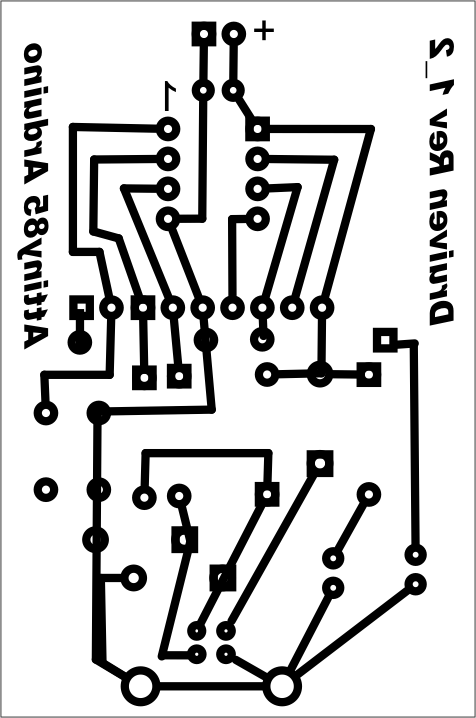
I used Fritzing to lay out the circuit board. From Fritzing I export an etchable svg file which I bring into Corel Draw so that I can make the traces thicker and add text.


I like the way the Paperduino brings out the ATtiny85 pins to a female header so I did the same thing below the chip on my board. 22 gauge hookup wire can be used to connect to a breadboard.

The Digispark Arduino IDE package contains the driver installation. The red LED is on Digital pin 1 so the Blink program with the output set to pin 1 is all that is needed to verify operation. Change the Programmer to Digispark and the Board to Digispark (Tiny Core). You start with the board unplugged and after hitting Upload the IDE tells you to plug in the board. The breadboard version worked once and the circuit board a couple of times. Most of the time I end up with a USB Not Recognized warning from Windows. The computer sees it as an unknown device. Despite this the code has loaded on three occasions. I suspect something is going on in Windows.

Despite having problems with the Windows driver it did work a couple of times and my red LED is happily blinking away as I write this. I think of Blink as a kind of Hello World on my own home-made ATtiny85 based Arduino board. Nice!

Tuesday, July 1, 2014

8 x 8 LED matrix using 4017 and Arduino


  This years grade 12 Computer Engineering summative  challenge asked the students to control an 8 x 8 LED matrix using a 4017 decade counter to "scan" the columns and an Arduino to "sink" the rows. Examine the schematic below and you will see that control of any particular LED in the matrix is a matter of making the 4017 pin high and the Arduino pin low. The 4017 chip counts from one to ten and then resets but setting pin 15 high also causes a reset. Connecting pin 9 to 15 causes the ninth count to reset the 4017 back to 1. Our decade counter ends up counting one to eight. Clock pulses on pin 14 make the 4017 count up. The fastest possible digitalWrite(2, HIGH); digitalWrite(2, LOW) cycle from the Arduino is enough for the 4017 to respond.
   The usual logic for LED control is to use the Arduino pins to "source" the LED - to go high or "on". An examination of most Logic and microprocessor circuitry specifications will show that these circuits have a higher capacity to "sink" current. That means you need to connect the LED anode to power and the cathode to the Arduino pin. Making the pin low is the same as ground so a zero on the pin will cause the LED to glow. This is a reversal in our usual logic where one = on and zero = off. In this case we need to keep the Arduino pins high and send them low to turn on the LED.

Parts
Arduino UNO
Breadboard
4017
BL-M07C881 - 8x8 LED matrix
8 x 300 ohm resistors (I used an 8 x 470 ohm DIP)
jumper wires (I cut most to length to keep it neat)

Here are the pin-outs for the LED matrix:


STEP 1: Wiring

Matrix             4017
5 -----------------> 3
6 -----------------> 2
7 -----------------> 4
8 -----------------> 7
13 ---------------> 6
14 ---------------> 5
15 ---------------> 1
16 ---------------> 10

Matrix             Arduino via a current limiting resistor.
1 -----------------> 6
2 -----------------> 7
3 -----------------> 8
4 -----------------> 9
12 ---------------> 10
11 ---------------> 11
10 ---------------> 12
9 -----------------> 13

Don't forget to wire Arduino pin 2 to 4017 pin 14 for a clk input and pin 3 on the Arduino to to pin 6 on the 4017 to detect a count of 8. Wire 5V from the Arduino to pin 16 on the 4017 and tie the ground to 4017 pins 8 and 13.


Step 2 Testing

   Use Blink but change the output pin to 2. Disconnect the wires going to the Arduino pins 6 to 13 . Blink will pulse the 4017 slowly. Connect any one of the 8 disconnected leads to ground. The LEDs on that row should light up one after another. If you reduce the delay the LEDs will light quicker and quicker. A very short delay will make it seem as though the entire row is lit. POV or Persistence of Vision makes it seem as though all 8 LEDs are on at the same time when really only one is on at any given time. You will use this later to minimize the current draw on your circuit.

/*
  Blink
  Turns on an LED on for one second, then off for one second, repeatedly.
 
  This example code is in the public domain.
 */

 
// Pin 2 is our 4017 clock.
int clk = 2;

// the setup routine runs once when you press reset:
void setup() {                
  // initialize the digital pin as an output.
  pinMode(clk, OUTPUT);     
}

// the loop routine runs over and over again forever:
void loop() {
  digitalWrite(clk, HIGH);   // turn the LED on (HIGH is the voltage level)
  delay(1000);               // wait for a second
  digitalWrite(clk, LOW);    // turn the LED off by making the voltage LOW
  delay(1000);               // wait for a second
}

Step 3 Programming

In the checkmark example below I used an array to 'map' which LEDs I wanted to come on.

/*
 Test 4
 Test 4 Checkmark
 */
int del = 0; // clk width
int chk = 0; // check for reset signal
int row = 1; // row
int ct = 0; //array counter
int pattern[] = {0,0,0,0,0,0,0,1,
                       0,0,0,0,0,0,1,0,
                       0,0,0,0,0,1,0,0,
                       1,0,0,0,1,0,0,0,
                       0,1,0,1,0,0,0,0,
                       0,0,1,0,0,0,0,0,
                       0,0,0,0,0,0,0,0,
                       0,0,0,0,0,0,0,0};
int sensorPin = 3;
void setup() {
  Serial.begin(9600);
  Serial.println("Start");
  // initialize the digital pins as an output.
  pinMode(2, OUTPUT); //clk out
  pinMode(3, INPUT); // reset sense
  for (int i = 6; i <=13; i++){
    pinMode(i, OUTPUT);  
  }
  for (row = 6; row <=13; row++){
    digitalWrite(row, HIGH);  
  }
  reset();
} // setup

void loop() {
    for (row = 6; row<=13; row++){
      for(int i=1; i<=8; i++){
        if(pattern[ct]==1){    
        digitalWrite(row, 0);
        pulse();
        delay(2);
        digitalWrite(row, 1);
        }
        else{
          pulse();
        }
        ct++;
    }
  }
ct=0;
}

void pulse(){
      digitalWrite(2, HIGH);
      delay(del);            
      digitalWrite(2, LOW);  
      delay(del);  
      // 8 pulses for 8 rows
}

void reset (){
  for (int i = 1; i<=9; i++){
    pulse();
    Serial.println(i);
    chk = digitalRead(sensorPin);
    Serial.println(chk);
    if (chk==1){  
      return;
    } // if
  } // for
} // function

If I were to do this again I would reverse the zeros and ones in pattern[] and then instead of using an if statement to check for a 1 I could have simply written the contents of the array out.
for(int i=1; i<=8; i++){  
        digitalWrite(row, pattern(ct));
        pulse();
        delay(2);
        digitalWrite(row, 1);
        }
       ct++;
etc.

Another interesting experiment would be using Arduino Port D (pins 0 to 7) to control all 8 rows with one command. I usually avoid using pins 0 and 1 but in this case it seems sensible to use them.

Step 4 Challenge

The challenge that earned top marks was to make a set of initials scroll across the matrix. In the example below I used a 2 dimensional array to 'map' the LEDs in a way that would make shifting them easier.
/*
 Test 5
 Scrolling Checkmark
 Implements 2 dimensional array
 */
int del = 0; // clk width
int chk = 0; // check for reset signal
int row = 1; // row
int ct = 0; //array counter

int pattern[8][16] = {
  {0,0,0,0,0,0,0,1,0,0,0,0,0,0,0,1},
  {0,0,0,0,0,0,1,0,0,0,0,0,0,0,1,0},
  {0,0,0,0,0,1,0,0,0,0,0,0,0,1,0,0},
  {1,0,0,0,1,0,0,0,1,0,0,0,1,0,0,0},
  {0,1,0,1,0,0,0,0,0,1,0,1,0,0,0,0},
  {0,0,1,0,0,0,0,0,0,0,1,0,0,0,0,0},
  {0,0,0,0,0,0,0,0,0,0,0,0,0,0,0,0},
  {0,0,0,0,0,0,0,0,0,0,0,0,0,0,0,0}
};
int ab=0;
int sensorPin = 3;
void setup() {
  Serial.begin(9600);
  Serial.println("Start");
  // initialize the digital pins as an output.
  pinMode(2, OUTPUT); //clk out
  pinMode(3, INPUT); // reset sense
  for (int i = 6; i <=13; i++){
    pinMode(i, OUTPUT);  
  }
  for (row = 6; row <=13; row++){
    digitalWrite(row, HIGH);  
  }
  reset();
} // setup

void loop() {
  for(ct=0; ct<8 animation="" croll="" ct="" p="">    for (int draw = 0; draw<5 down="" draw="" p="" slow="">      for(int row=0; row<8 p="" row="">        for(int col=0; col<8 col="" p="">          if(pattern[row][col+ct]==1){    
            digitalWrite(row+6, 0);
            pulse();
            delay(2);
            digitalWrite(row+6, 1);
          }
          else{
            pulse();
          }
        }//col
      } //row
    }//draw
  }// ct
} // main loop

void pulse(){
  digitalWrite(2, HIGH);
  delay(del);            
  digitalWrite(2, LOW);  
  delay(del);  
  // 8 pulses for 8 rows
}
/* The reset function is called once during setup.
 It pulses the 4017 until it detects an output from
 pin 6, indicating that the count is at 8 and the next pulse
 will be column 1. */
void reset (){
  for (int i = 1; i<=9; i++){
    pulse();
    Serial.println(i);
    chk = digitalRead(sensorPin);
    Serial.println(chk);
    if (chk==1){   // 4017 pin 6 is high
      return; // No need to continue
    } // if
  } // for
} // function

The array is twice as wide as the matrix to allow a frame 'buffer'. There are probably better ways to manipulate the array to do this.