Thursday, March 26, 2020

Converting a 2418 Desktop CNC to Laser part 1

I had been toying with the idea of swapping the spindle motor for a laser on my 2418 desktop CNC machine. The Woodpecker 2.6 controller has a laser output which is straight ON/OFF but I wanted to use a 5.5 W PWM controlled 450 nm blue laser so that I could adjust the laser power on the fly. The Laser I found on line is made by WonVon and comes with a controller with 12V and TTL (PWM) inputs. The software I found is similar to the GRBL software I used for CNC work and is called LaserGRBL v3.1.2.  I believe what I found out will work for any PWM controller laser running any CNC/Laser type software using the GRBL controller.

I discovered that the Atmega 328 that is the brains on the Woodpecker is the same chip used on an Arduino. It had a boot loader called GRBL 0.9 but I needed to upgrade to 1.1 to be able to control a laser. There are a lot of instructions and discussions available showing how to do this on an Arduino but nothing clear for the Woodpecker. Fortunately, there is a utility built into LaserGRBL that flashes the 1.1 firmware (bootloader) with the push of a button. The USB interface to the Woodpecker uses a CH340 chip and LaserGRBL also has a utility to install the driver. Both utilities are in the menu bar under Tools.

I thought that the PWM pin that the S command (laser intensity) in G code was available on the 34 pin header. Sadly I was mistaken. The signal originates from the D11 pin on the Atmega 328. On the Woodpecker the 328 is too small to solder directly but D11 connects to the big power MOSFET that controls the spindle. You can see I soldered a short piece of blue solid 22 gauge wire directly to the MOSFET signal pin in the photo below. The brown ground wire is a female 0.1 jumper end. Both of these are spliced to the PWM input. White is PWM + and yellow is ground. The other connector in the photo with yellow and white wires connect to an external 12V DC power supply. On this connector yellow is + and white is ground.


I also thought it would be nice to easily switch between Laser and Spindle mode on the 2418. I hoped the spindle motor clamp was the right size to also hold the laser. Again, sadly I was mistaken. Fortunately I found that Brandon Piner had published some stl files on Hackaday that showed promise. His CNC Z Mount allows the easy exchange of tools. Brandon also put his files on Thingverse where a remix by wb-maker gave me a mount for my laser. Now all I needed was a mount for my spindle motor. I drew this out in Inventor and then got all three parts, the Z Mount, the laser mount and the spindle mount printed.

The next 3 photos show the Z Mount, the Z mount with the laser attached and the Z mount with the spindle mount attached.


In order to use the new Z mount I had to push the 4 bearings and lead screw adapter out of the original spindle mount and then push them back into the new Z mount. I was careful to use objects like bolts that were the same diameter as the bearing or adapter to gently tap them out/in. To push them out I supported the block on a solid surface with a hole large enough to receive the bearing or adapter. To push them in I made sure the parts had a thin coat of oil and were held square to the hole. No excessive force was needed.

In part 2 I will talk about getting the software set up and using LaserGRBL to do line art and grey scale bitmaps.


Thursday, July 5, 2018

Tiny Duino board on a desktop CNC


This photo shows 3 versions of the Tiny Duino board I first described in July 2014. The board on the right is laid out in Fritzing and etched using the toner transfer method to create a mask. The other 2 boards were laid out using Eagle and produced on my little desktop CNC machine seen in my October 2017 post. The default components in Eagle are good for commercial production but created pads and lines that were too fine for this method.

The first step was to learn a little about Eagle CAD. Eagle is free for hobbyists making small single sided or double sided circuit boards. You can edit components by opening the library containing the component and then double-clicking the package file for the component. I made the pads bigger and the drill holes smaller. Later when the CNC machine does the drilling the hole size is determined by the physical drill you place in the machine. I used save-as and put "my" in front of the library name to make it easier to find later. You will need to open your new libraries using the Library manager in order to be able to use them. You can find some tutorials online to learn more about this. In Eagle 8.6 the component libraries are in /cache/lbr. I put the libraries I edited into Github. Library files contain large collections of components. I only edited the components used on the TinyDuino.

Since I had already laid out the TinyDuino board for etching I found it quicker to place the components on a new board in Eagle and then create the traces. This takes 2 steps. Firstly use Signal to join the components and then Route to create the trace. You can move the traces around and create bends. I made the traces 20 to 30 wide. Ground traces that are wider then the rest make it easy to identify ground later on. Make sure they are all on the Bottom since you are making a single-sided board.

TinyDuino layout

The Make Your Own PCBs on an Inexpensive Desktop CNC machine Instructable article by davr.org helped me figure out how to use EagleCAD to generate the G code for my own desktop cnc mill. The pcb-gcode-EagleCAD plugin file contains a good manual in the docs folder to help you figure out the next steps. The plugin uses Processing and also generates a graphic so that you can double check your G Code. I used the single pass isolation mode and a 0.5mm end mill. Keep the spindle speed high, the feed rate low and run the code with the bit cutting air first to make sure the code works.

G code visualizer from the Eagle plugin.

Everything about this project required learning, trial and error and time. I was very pleased to see the final TinyDuino boards being cut. There were several trials until I got everything right. I think it really helped to do this with a circuit board that I am already very familiar with. I feel more confident that I can use this method to make a prototype circuit board in the future.

Friday, October 27, 2017

Retired!

Happy Friday . . if you happen to be reading this on a Friday! So I am officially retired from teaching. I sleep in, read books, do errands and wonder where the day went! I still mentor for FRC team 4992 so I'm back in to the school two afternoons a week. I will do some supply work but otherwise my schedule is pretty clear. I planned to spend some more time on this blog and perhaps widen the scope a little but here it is already the end of October and I am finally sitting down to get at it. The first order at hand was to be a comprehensive list of Microntrollers but thanks to ZeusGuy, Graeme Bartlett et al there is now a nice long list on Wikipedia. Good job people.

The teachers in my department all pitched in and got me this neat little desktop CNC machine for my retirement gift. In the next couple of blog posts I'll talk about using Eagle CAD to generate G code files to make small circuit boards on this machine.


Saturday, August 19, 2017

A First Look at the mBot

Recently our school board received some mBots from Makeblock to try out in the classroom. The mBot is a small autonomous Arduino Uno based rover educational platform that can be programmed in Arduino C or a Scratch derivative called mBlock (mBlockly on an iPad).

The kit comes with the following:
mCore main board, DC motors, wheels, chassis, battery holder, hardware
INPUTs: Light Sensor, Button and IR Receiver on board and an Ultrasonic Sensor module and a Line Follower Sensor Module. The modules plug in via RJ25.
OUTPUTS: 2 RGB LEDs, Buzzer, IR Transmitter, 2 motor ports on board.
Each kit comes with either a WiFi or Bluetooth module that sits on mainboard headers.
POWER: Standard female DC power jack or standard Lithium 2.0 connector.

The sensors plug in to RJ25 jacks and the motors have 2 pin JST connections. There are 4 available RJ25 jacks. 1 and 2 contain Arduino I/O pins 9 through 12. 3 and 4 contain Arduino A0 through A3 pins. There is an ICSP header. There are no other I/O ports supplied. There are solder points for two 0.1" x 6 headers. On the left is A0, A1, A2, A3, SDA, SCL and on the right is GND, 5V, 9, 10, 11, 12.

The kit also comes with an IR remote (requires a CR2025 cell), a USB cable and a hex driver for assembly. Putting it together takes no time. The main board needs to be removed to change batteries if you are using AA cells. The main board supports charging Lithium batteries which are not included but might make a wise investment considering the way DC motors use up battery power.

Straight out of the box I had the mBot running in no time. The default program lets you control the mBot via Bluetooth (or WiFi), or via IR or it can be set to autonomous run around and avoid obstacles mode or line-following mode. I like the mBlock IDE because you can quickly program the mBot using Scratch-like blocks and see the Arduino C code result in the right hand window. This makes for an easy transition for grade 9 or 10 students who have used Scratch and want to start coding in C.


I think the mBot is a good platform for teaching robotics, interfacing or Arduino to grade 9 and 10 students. The price is very good. We purchased a similar all-in-one platform a few years ago that needs to stay tethered via a USB cable to work. The old platform engages students but can be frustrating because the tether cable limits motion. The mBot should be operated on the floor but drops and kicks will be inevitable. The mBot is very robust. The metal chassis can handle some pain. Parts like wheels and DC motors are easy to replace. The kit comes in a handy reusable box that can hold the mBot after assembly and stack in a cupboard.

I usually shy away from endorsing products but this unit deserves mention for its competitive price and ease of use. I would recommend these to anyone starting out high school Computer Tech or Robotics classes. A class set might be impossible to budget in one year but as I always recommend - have a plan. Buy 2 or 3 a year. These units will do a great job at covering many of the learning outcomes in TEJ courses.

Sunday, June 5, 2016

The Internet of Things part 1, the Yun

In the Internet of Things series I will explore the use of WiFi enabled microprocessors like the Arduino Yun and Digispark Oak as tools that students can use to learn how to connect devices to the Internet. The connection of devices and machines to the Internet to allow man-machine and machine-machine interaction is now embodied in the phrase "the Internet of Things". There has been an explosion of interest in industry and commercial markets as the price of WiFi technology comes down. A corresponding surge in the hobby, DIY field can be seen with an ever growing number of products and online tutorials and projects. The Yun was first released in 2013 with the same form factor and IDE as the original Arduino. Recently we saw the release of the Raspberry Pi 3 which has 802.11n and Bluetooth built in. The Digispark Oak, the Omega Onion and a host of other products aimed at the hobbiest, DIY and developer fields are becoming available.

In this post I will write about my first few experiments with the Yun. In the next few posts I will describe early experiments with the Oak and other WiFi enabled microcontroller solutions. I hope to be able to conclude with a wish list for enabling students to learn about this technology in a clean and consistent manner. My early experience with the Yun and Oak indicate that the technology is not straight forward nor for the faint of heart. I hope to finally compare and contrast all the solutions that I tried out.

The first step as it is with any of these things is to follow the Getting Started tutorial that comes with the device. I found that I could connect the Yun easily to my home network (Linksys) or my experiment router (Belkin with no Internet). At school I should be able to connect to our public network since the Yun does not require any special settings at the router. Some familiarity with ip addressing and the Linux OS helps but is not necessary.

"The Arduino Yún is a microcontroller board based on the ATmega32u4 and the Atheros AR9331. The Atheros processor supports a Linux distribution based on OpenWrt named Linino OS. The board has built-in Ethernet and WiFi support, a USB-A port, micro-SD card slot, 20 digital input/output pins (7 of them can be used as PWM outputs and 12 as analog inputs), a 16 MHz crystal oscillator, a micro USB connection, an ICSP header, and 3 reset buttons." - from the Arduino.org website.

The Atheros processor communicates with the ATmega microcontroller using a technology called Ciao Core.  This technology is incorporated into the Bridge library which must be included in your sketches.

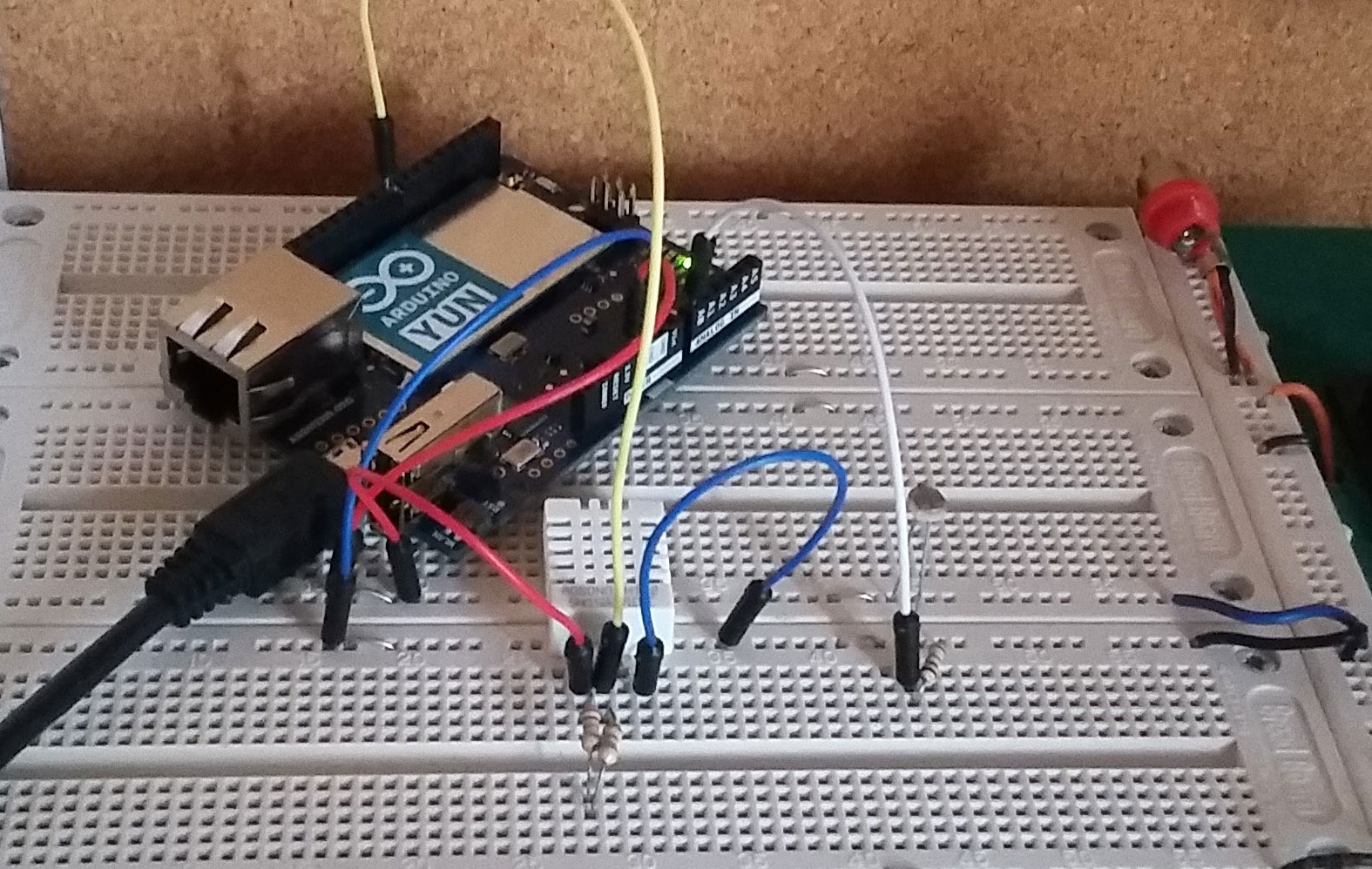
Step 2 involved using the Yun just like any other Arduino to verify the correct operation of the following devices:
1. Photoresistor in series with a fixed resistor to measure analog light levels.
    Photoresistor wiring from Arduino Tutorial.
2. DHT22 to measure temperature and humidity. DHT22 wiring from Make Nation.

The sketch worked perfectly using the open source DHT22 Arduino library.


Step 3 used the Weather Station tutorial in Marco Schwartz's book the Internet of Things with the Arduino Yun. The tutorial uses a website/software stack called Temboo as a go-between a Yun and cloud apps like Google docs. You will need to have a Temboo account and a Google account.

Marco's book is 2 years old and Google has changed the way docs are accessed. Instead of good old username and password Google now uses the oAuth protocol. The Temboo website uses apps they call choreos that enable the flow of data from the Yun to be entered onto a spreadsheet. In order to set up a connection you must now run an initialization oAuth choreo and a Finalize oAuth choreo. As you go through the process you collect a client id, app id and other tokens that have to be copied into your code. You can follow the Temboo tutorial which gives you some Arduino Yun code that works. You can find my code, which integrates the original code from the book and the Temboo tutorial on Github. https://github.com/mdruiven/Yun-Weather-Station. All the account information and tokens are in a separate file called TembooAccount.h. Make sure to change them to your own codes and information.

I found that I had to use my coding skills to solve a couple of issues. I think the level of complexity was medium to hard and beyond the average high school level. That said, I believe that senior high school students could tackle problems very similar to this one by following these directions and using my code. By similar I mean write some data to a spreadsheet collected from various sensors connected to a Yun. I think this has a very high cool factor and will encourage students, and others, to continue to learn and experiment with this technology.


Saturday, August 15, 2015

Rare and Cherished part 2

Now that the Pan Am and Para Pan Am games are over it is time to reflect on the experience I referred to on April 12, In that post I outlined a plan to allow students to use voluntary IT support work at the games as  high school coop hours. Over all this was a positive experience for the students but there were some hitches along the way.

Throughout May and June the students continued to self organize their on line and in person training and the collection of credentials from North York in Toronto. The students also received their shifts and it quickly became apparent that I had overlooked one important factor. Hours. High school students need to complete 180 hours on the job in order to earn their 2 credits. Most of the students did not have near enough shifts to make up these hours. Furthermore some students were conflicted out of the coop course by the necessity of summer make up credit classes. The students had to make up hours by taking on other coop positions at local IT related businesses or by completing some in school hours doing IT related work.. Some elected to give up their Pan Am shifts and work at local IT shops instead. Lesson learned? I should have asked for direct involvement in the students' scheduling at the games. Did it matter? Not much. The students did an excellent job tracking their own hours and all of them had great experiences at the games and at other placements. The students dealt with the "hours" problem through good problem solving and collaboration.

During a Pan Am games "test event" at the Milton Velodrome I elected to drop by to see how one of my students was doing. In a normal coop placement the coop teacher visits the students on sight on several occasions to familiarize themselves with the work place, discuss the learning objectives with the placement supervisor and check for student health and safety requirements. At the test event I had no problem locating the student and viewing the workplace. The volunteer that helped me find the right room was a teacher herself and understood my reason for being there. I was not prepared for the increased level of security at the actual Pan Am Games. Without some form of accreditation I was not going to be allowed onto the sight. The security staff were volunteers themselves and were just doing their job according to the rules. I had to be satisfied with brief emails, a couple of phone contacts and one face to face with a Cisco engineer. Bear in mind that the students' supervisors were themselves volunteers. Lesson learned? If it is a world class event you must have accreditation. Did it matter? Not much. The Pan Am games structure was very well organised and we already had a good look into that organization during our webinar sessions during the last 18 months. The students received good feedback from their supervisors at the games.

After reading the students' reflections and attending some Pan Am events myself I feel confident that the students had memorable and worthwhile experiences. They learned varying amounts about computers and networks but they all gained a good deal of confidence at communication, problem solving and teamwork. I think the Pan Am experience taught us that the GTA can handle any event, no matter the size and it taught me that my students are ready to be leaders in the next big one.

Wednesday, June 24, 2015

Neopixels and ATTiny 85 Arduino shields

This semester the grade 12s had to come up with a unique application of Neopixels using their own ATTiny 85 Arduinos that they built at the start of the semester. The application is implemented on an ATTiny 85 shield that the students design and etch in the classroom.  The shield interconnects the ATTiny 85 Arduino, a strip of 12 Neopixels and a DC Wall adapter type power supply. The shield uses a 9 pin header to connect to the home brew Arduino and screw terminals to connect the power supply and the Neopixel strip.


In earlier blogs I described the very successful ATTiny 85 home brew Arduino my students build in their high school classroom and some grade 12 challenges involving the design and construction of Arduino shields. Last semester the students built motor driver Arduino shields to operate two stepper motors extracted from surplus CDROM drives. The motors were used to drive a CNC pencil built on a simple wooden frame.  Another common challenge I have used in the past is a traffic light simulator built onto a shield. While very successful units were built the students could not work further with their shields unless they purchased their own Arduino Uno.  This year the students could put together their own ATTiny 85 Arduino with a shield to build a project that they can take home.

The shield needs to

  1. provide 5V power to the Neo pixel strip and the ATTiny 85 Arduino.
  2. provide a connection point for the Neopixel strip data and power
  3. contain a 9 pin header to connect to the ATTiny 85 Arduino.
  4. provide connections or house some kind of input such as a momentary push button, light sensor etc.
1. Power. 
The shield needs to support the large 1000 uF capacitor along with a 7805 regulator that takes anywhere from 5 to 25 volts input and keeps the output pin at 5V. C2 provides rf filtering at 0.1 uF. In the photo above you can clearly see the 7805 in front of the large 1000uF capacitor. 6, 7.5 and 9 volt adapters, 200mA or more worked best. 12 and 15 volt adapters caused the 7805 to reach temperatures of 140 degrees C when all 12 pixels were on at full power - white. A couple of students worked directly from 5 volt adapters and had no problems. 5 V switching power supplies are recommended. 30 Neopixels can draw a whopping 2 A current.

2. Connection point.

J1 and J2 are power in and 5V power out. By combining the 2 ground screws into one screw we can use the last unused screw terminal for the data - out to the Neopixel shield. Many of the student designed shields also provide connection points for external sensors.  The shield shown above contains 2 push buttons and between the 7805 and the capacitor is a 3 pin header providing power and data to and from any Arduino compatible sensor. This is the layout for the board shown above done in Fritzing. Soldering wires to the Neopixel strip proved to be a little difficult. Too much stress on the connection will cause the copper to delaminate from the plastic and break off. We glued the pixels down with double sided tape to help prevent this from happening.


3. 9 pin header

The 9 pin header connects our shield to the ATTiny 85 as shown in the photo above. In the diagram the top pin is 0, ground.
1 is unused. On the ATTiny 85 Arduino pin 1 is the reset button.
2 is an extra input for an analog sensor - logical Pin 3.
3 S1 (pushbutton) - logical Pin 4.
4 is unused. It is another ground.
5 Neopixel data - logical Pin 0. In the next revision I will add a 300 ohm resistor in series between the header and the screw terminal to help protect the Neopixels from excessive current on the data line.
6 is unused.
7 S2 (pushbutton) - logical Pin 2.
8 5V power.

4. I soldered in a small 3 pin female 0.1" header so that I could easily connect a sensor that provides an analog or digital voltage.  From top to bottom: data, +5V, gnd.

Here are some examples of the boards and functions the students came up with.

A game using counters.
 

Light pattern selected by pushbuttons.

Light pattern controlled by a single push button.

Other projects included:
- tic tack toe
- lights controlled via bluetooth from a smart phone
- lights controlled via an ultrasound ping detector
- lights controlled by a temperature sensor