Sunday, January 15, 2023

Balance on a Teeter totter

 This year the FRC robots need to balance on a teeter-totter affair on the playing field. 


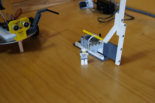
This video shows an autonomous ESP32 robot attempting to balance itself. I don’t have a gyro at home so I used a 3 axis compass (which gets thrown off when the robot changes direction). I think it will be easier to do with a real gyro. The drive system is cheap continuous rotation servos driven by an ESP32. It is next to impossible to get the servos synced at the same power level and to slow them down, so, again with a real robot that drives straight and slow this enterprise would be improved. Once I sorted out some power issues and a bum servo it was satisfying to see it work.

The code is a simple if structure.

If the x axis is greater than 100 (pointed up) drive forward a bit and wait a bit;
Else If the x axis is less than -100 (pointed down) back up a bit and wait a bit;
Else wait a bit;

Saturday, March 12, 2022

ESP32 mini home robot for E-learning


Last school year in Ontario all the classes were on line and clubs and sports teams just weren't happening. The team at CKSS, Sparbotics, Team 4992 continued to meet on line through the fall of 2021 and spring of 2022. Team members entered 3 FIRST Robotics virtual challenges under the Inifinite Recharge at Home banner. 20 team members also took home a desktop robot kit I designed around the ESP32 chip. The students learned some basic i/o skills (much like the Arduino) and then explored the Wifi capabilities following a set of instructions and meeting online with questions and observations. The school year culminated with the Mission to Mars challenge which asked the students to move a lego "cargo" brick between 2 stations.

High School students had great difficulty with the online learning environment. Students learn best by doing and the "doing" needs to be in an environment they are accustomed to. They work best with their peers at solving problems and asking questions. They liked working on the Infinite Recharge at Home challenges together but many lost enthusiasm with the ESP32 because they were working alone, unable to see each other and see the other robots. The ESP32 challenges would have worked better in an immersive virtual environment with VR glasses or cameras showing the students, their screens and their hands working on the robots. I can't imagine getting to place where that could happen given the amount of technology required and the privacy concerns it would raise.


Tuesday, March 30, 2021

Interesting facts and ideas from a People for Education Report titled Technology in Schools.

This People for Education Report is an important read.

From the report:
"Up to now, future-ready skills and competencies have gone by a variety of labels including soft skills, 21st century skills, transferable skills, and global competencies (British Columbia Ministry of Education, 2017; OECD, 2018; RBC, 2018; Waddell et al., 2018). People for Education refers to them as The New Basics."

1. Thinking Creatively and critically
2. Developing a Sense of Self and Society
3. Communicating Effectively
4. Learning to learn
5. Collaborating

In Ontario "future ready" skills are referred to by the Ministry of Education as "transferable skills" including, 
1. critical thinking
2. social-emotional skills
3. adaptability
4. digital literacy
5. collaboration

While 1, 2 and 5 in both lists are a match, 3 & 4 are not. Adaptability & Digital Literacy are both open to interpretation more than the other 3 so it remains to be seen how these terms will be used in curriculum documents.


Thursday, April 9, 2020

Converting a 2418 Desktop CNC to Laser part 2

In part 1 I talked about the mechanical and wiring portions of the conversion. In part 2 I will discuss software settings and usage along with operation. Now that the laser is mounted and wired it's time to burn some wood!

The LaserGrbl software lets you change some of the Grbl firmware settings on the controller board. I left everything as is except $3 which I had to invert so that the X and Y movements on the mill matched the output from the software.


I started out powering the laser using an old 1 amp variable voltage power supply I built many years ago. I figured 12 volts, 5.5 W, that's less then 1/2 an amp right? Wrong. My initial try with the included griffin example file (look for the sample SVG - G Code folder) went well but after that the laser output started becoming erratic and would trail off after a few seconds. A quick test with a multimeter showed the power supply voltage was dropping to just 3 or 4 volts! 


A week or so later when I got a fixed 12V 5A power supply I was able to start experimenting again. LaserGRBL lets you make custom buttons. Right click and choose Add Custom Button in the button bar at the bottom. This one turns the laser on at low power (25/255).


I do not have limit switches so Grbl uses the XY position at power on as home. I make sure the laser is positioned on the lower left area of the workspace when I power up and then use this low power laser on/off button to give me a low power dot to position the work piece. Getting the laser focused was tough because even at the low power setting the wood begins to burn after a few seconds. Focusing took some patience as I had to keep moving a scrap piece while turning the focusing ring and looking for the smallest dot. It paid off because now it draws very sharp lines. I am using scrap pieces of 1/8" mahogany construction grade plywood.


After experimenting with laser power settings and feed speeds I came up with a combination that gave good clean lines and corners. I drew the iceboat outline by tracing a photo using Aspire and then exporting it in svg format. LaserGrbl generated the CNC code from the .svg file. On import the software asks for the feed speed and laser power settings. The code did not complete the lines in a logical order, often wasting time jogging back and forth. I still need to investigate why this is happening. 

Doing something with grey scale in it like a photo is the next challenge. Wood is either burned or not. LaserGrbl creates grey scale areas by using dots, the more space between the dots, the lighter the shade. The trick seems to be feeding LaserGrbl with a photo that is comprised of a narrow scale from light to medium grey.


I imported this grey scale file to try some test strips at different feeds and power settings.


Coming up I'll experiment with photos some more and then move on to cutting paper and wood.


Thursday, March 26, 2020

Converting a 2418 Desktop CNC to Laser part 1

I had been toying with the idea of swapping the spindle motor for a laser on my 2418 desktop CNC machine. The Woodpecker 2.6 controller has a laser output which is straight ON/OFF but I wanted to use a 5.5 W PWM controlled 450 nm blue laser so that I could adjust the laser power on the fly. The Laser I found on line is made by WonVon and comes with a controller with 12V and TTL (PWM) inputs. The software I found is similar to the GRBL software I used for CNC work and is called LaserGRBL v3.1.2.  I believe what I found out will work for any PWM controller laser running any CNC/Laser type software using the GRBL controller.

I discovered that the Atmega 328 that is the brains on the Woodpecker is the same chip used on an Arduino. It had a boot loader called GRBL 0.9 but I needed to upgrade to 1.1 to be able to control a laser. There are a lot of instructions and discussions available showing how to do this on an Arduino but nothing clear for the Woodpecker. Fortunately, there is a utility built into LaserGRBL that flashes the 1.1 firmware (bootloader) with the push of a button. The USB interface to the Woodpecker uses a CH340 chip and LaserGRBL also has a utility to install the driver. Both utilities are in the menu bar under Tools.

I thought that the PWM pin that the S command (laser intensity) in G code was available on the 34 pin header. Sadly I was mistaken. The signal originates from the D11 pin on the Atmega 328. On the Woodpecker the 328 is too small to solder directly but D11 connects to the big power MOSFET that controls the spindle. You can see I soldered a short piece of blue solid 22 gauge wire directly to the MOSFET signal pin in the photo below. The brown ground wire is a female 0.1 jumper end. Both of these are spliced to the PWM input. White is PWM + and yellow is ground. The other connector in the photo with yellow and white wires connect to an external 12V DC power supply. On this connector yellow is + and white is ground.


I also thought it would be nice to easily switch between Laser and Spindle mode on the 2418. I hoped the spindle motor clamp was the right size to also hold the laser. Again, sadly I was mistaken. Fortunately I found that Brandon Piner had published some stl files on Hackaday that showed promise. His CNC Z Mount allows the easy exchange of tools. Brandon also put his files on Thingverse where a remix by wb-maker gave me a mount for my laser. Now all I needed was a mount for my spindle motor. I drew this out in Inventor and then got all three parts, the Z Mount, the laser mount and the spindle mount printed.

The next 3 photos show the Z Mount, the Z mount with the laser attached and the Z mount with the spindle mount attached.


In order to use the new Z mount I had to push the 4 bearings and lead screw adapter out of the original spindle mount and then push them back into the new Z mount. I was careful to use objects like bolts that were the same diameter as the bearing or adapter to gently tap them out/in. To push them out I supported the block on a solid surface with a hole large enough to receive the bearing or adapter. To push them in I made sure the parts had a thin coat of oil and were held square to the hole. No excessive force was needed.

In part 2 I will talk about getting the software set up and using LaserGRBL to do line art and grey scale bitmaps.


Thursday, July 5, 2018

Tiny Duino board on a desktop CNC


This photo shows 3 versions of the Tiny Duino board I first described in July 2014. The board on the right is laid out in Fritzing and etched using the toner transfer method to create a mask. The other 2 boards were laid out using Eagle and produced on my little desktop CNC machine seen in my October 2017 post. The default components in Eagle are good for commercial production but created pads and lines that were too fine for this method.

The first step was to learn a little about Eagle CAD. Eagle is free for hobbyists making small single sided or double sided circuit boards. You can edit components by opening the library containing the component and then double-clicking the package file for the component. I made the pads bigger and the drill holes smaller. Later when the CNC machine does the drilling the hole size is determined by the physical drill you place in the machine. I used save-as and put "my" in front of the library name to make it easier to find later. You will need to open your new libraries using the Library manager in order to be able to use them. You can find some tutorials online to learn more about this. In Eagle 8.6 the component libraries are in /cache/lbr. I put the libraries I edited into Github. Library files contain large collections of components. I only edited the components used on the TinyDuino.

Since I had already laid out the TinyDuino board for etching I found it quicker to place the components on a new board in Eagle and then create the traces. This takes 2 steps. Firstly use Signal to join the components and then Route to create the trace. You can move the traces around and create bends. I made the traces 20 to 30 wide. Ground traces that are wider then the rest make it easy to identify ground later on. Make sure they are all on the Bottom since you are making a single-sided board.

TinyDuino layout

The Make Your Own PCBs on an Inexpensive Desktop CNC machine Instructable article by davr.org helped me figure out how to use EagleCAD to generate the G code for my own desktop cnc mill. The pcb-gcode-EagleCAD plugin file contains a good manual in the docs folder to help you figure out the next steps. The plugin uses Processing and also generates a graphic so that you can double check your G Code. I used the single pass isolation mode and a 0.5mm end mill. Keep the spindle speed high, the feed rate low and run the code with the bit cutting air first to make sure the code works.

G code visualizer from the Eagle plugin.

Everything about this project required learning, trial and error and time. I was very pleased to see the final TinyDuino boards being cut. There were several trials until I got everything right. I think it really helped to do this with a circuit board that I am already very familiar with. I feel more confident that I can use this method to make a prototype circuit board in the future.

Friday, October 27, 2017

Retired!

Happy Friday . . if you happen to be reading this on a Friday! So I am officially retired from teaching. I sleep in, read books, do errands and wonder where the day went! I still mentor for FRC team 4992 so I'm back in to the school two afternoons a week. I will do some supply work but otherwise my schedule is pretty clear. I planned to spend some more time on this blog and perhaps widen the scope a little but here it is already the end of October and I am finally sitting down to get at it. The first order at hand was to be a comprehensive list of Microntrollers but thanks to ZeusGuy, Graeme Bartlett et al there is now a nice long list on Wikipedia. Good job people.

The teachers in my department all pitched in and got me this neat little desktop CNC machine for my retirement gift. In the next couple of blog posts I'll talk about using Eagle CAD to generate G code files to make small circuit boards on this machine.